PLANNING...
My initial plan called for a very simple 6'x6' square box with a basic roll-off roof. The idea was to build a barebones shed for imaging only that would simply house a pier/mount/scope and protect them from weather elements. At one point I've put together a quick mockup box out of scrap wood, placed my setup inside and quickly realized that 6'x6' was simply too restricting... so I started sketching out a 8'x10'' box, using my 8'x12' garden TuffShed as the blueprint to get the feel for the space. 8'x10'' seemed much better and I thought I settled on the size and started researching roll-off roof options.
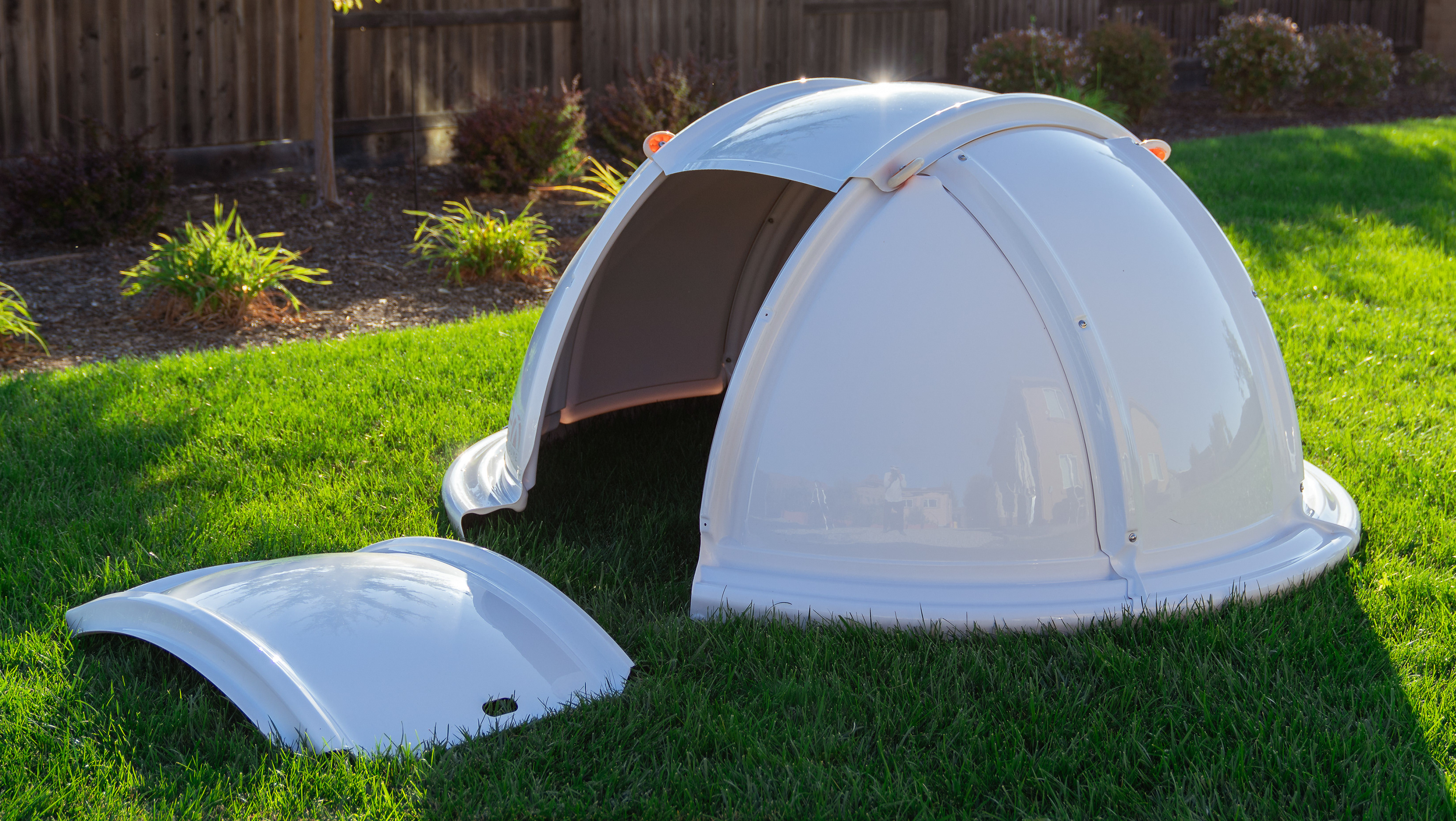
That's when I realized that I didn't really care for the typical roll-off designs. I've tinkered with a few ideas on paper on how to make the roof less bulky, how to hide the unsightly support beams and columns, how to better seal the gaps from rain, dust, etc. Nothing I came up with seemed all that clever. Then I took a step back and thought, since I'm going through the trouble of building a more substantial structure than I initially planed for, what are ALL the issues that I should be addressing: space, weather, protection from wind and stray lights during imaging, future mount/scope upgrade options, automation. In talking this over with my wife, I mentioned a dome and she said - why don't you just do that? And that was that... I did my homework on dome options and settled on an 8' dome from NexDome as the most practical option (more on this later).
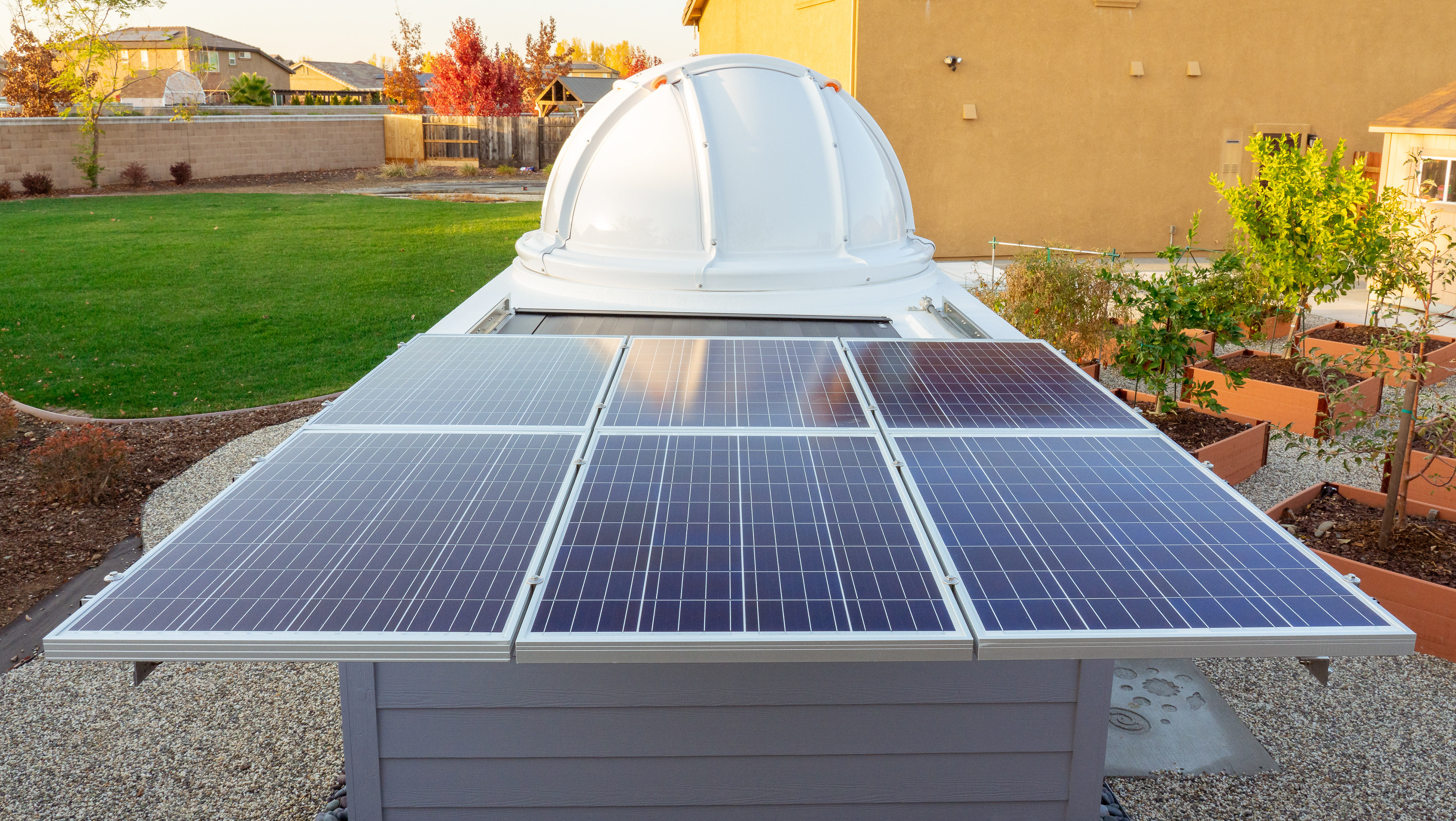
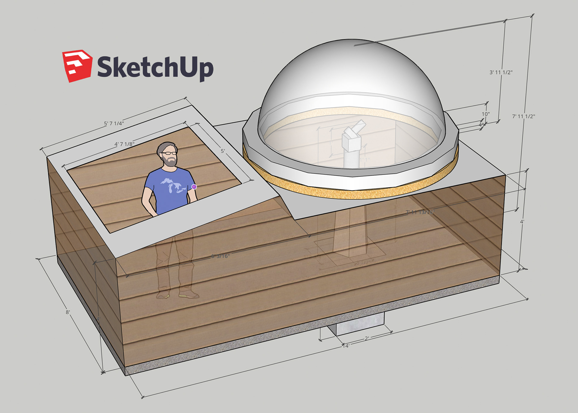
I've used Google's SketchUp to build a 3D model of what the final observatory could look like and used this pretty cool software to jot down actual measurements, get the feel for space, etc. As you can see, my original idea was to have a sloping roof with an opening, which eventually got reworked into a flat roof with solar panel slide above (more on that later!)
Deciding on a site
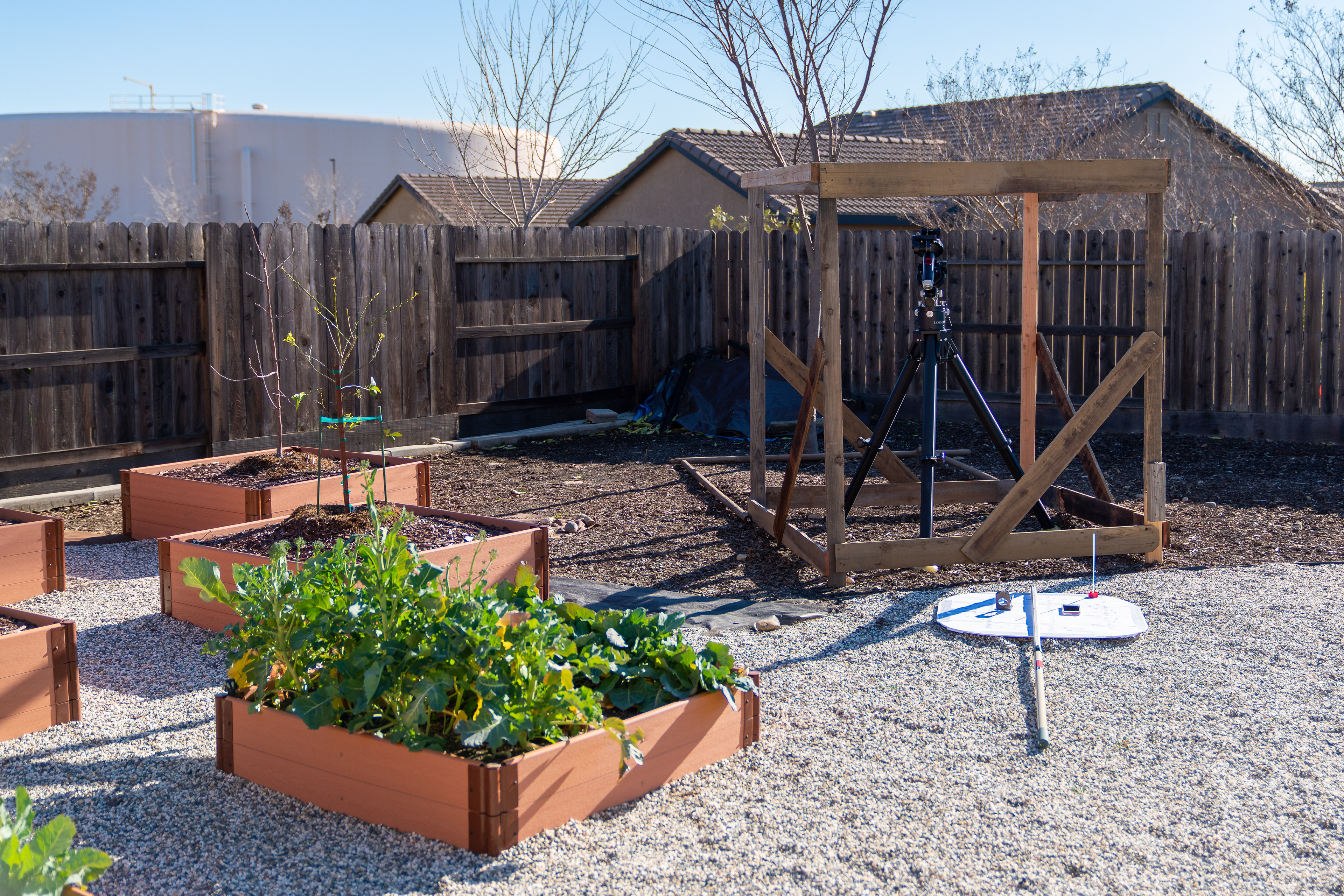
Mockup shed box to test for space, clearance, and visibility
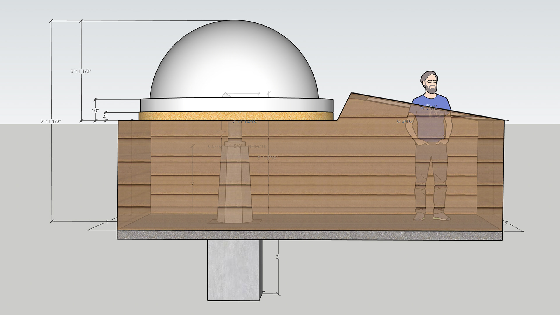
SketchUp modeling
BREAKING GROUND...
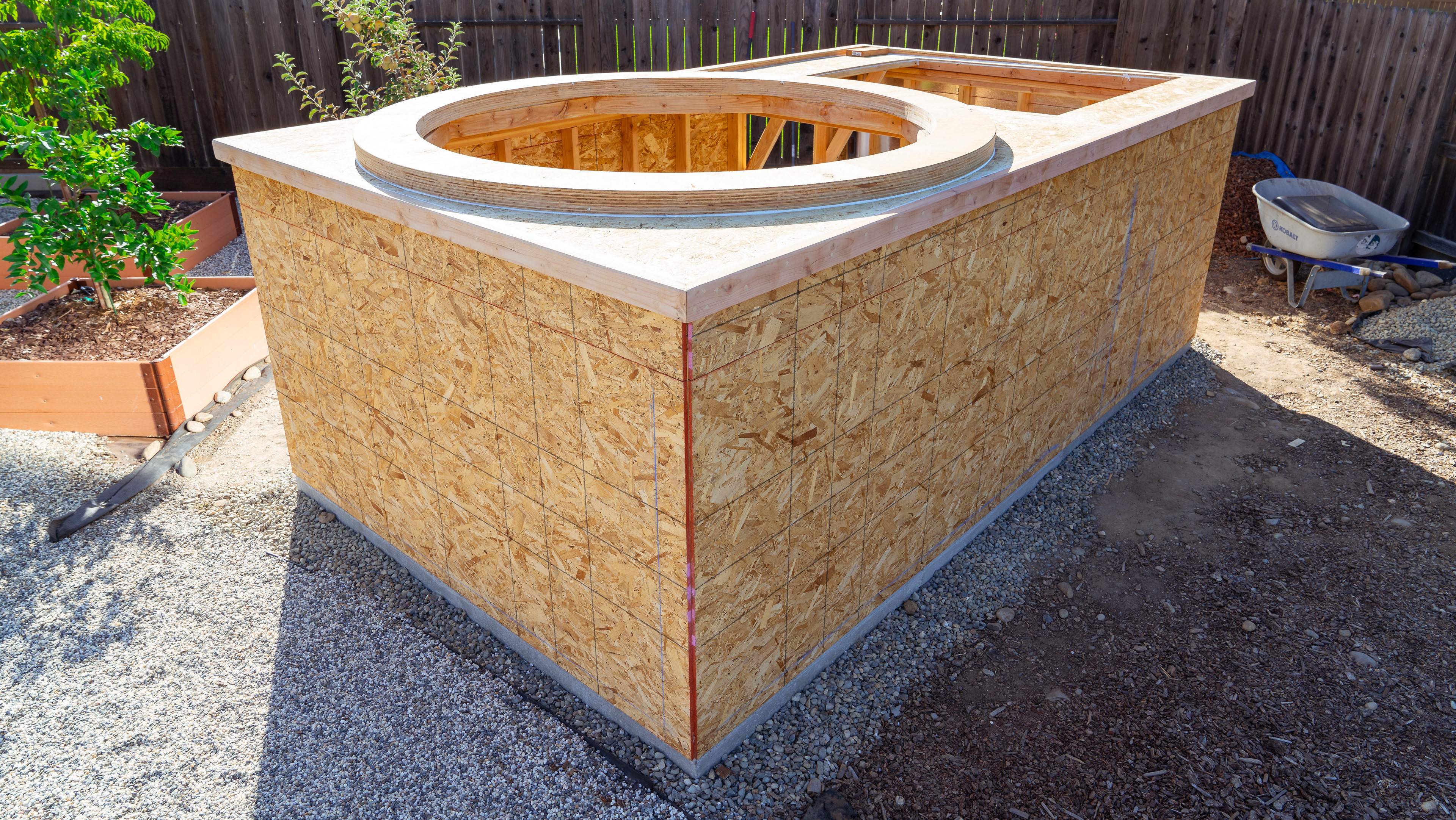
After settling on the dome option I've extended the floorpan further to accommodate 8'x8' box for the dome perimeter and additional 6'x8' for storage space for a total base of 8'x14'. Now it was time to clear the ground, center the location for the pier hole and... get to digging! I live in the Sacramento Valley, specifically in the Rancho Cordova where soil is mostly solid clay and football-sized boulders - this made digging a real pain. In doing my research on pier foundations, and learning about soil dynamics in the process, I've come up with base requirement of about 2'x5' deep and got to digging. At 2' I gave up on shovels and pic axes and rented a 35lbs jack hammer from HomeDepot. That helped quite a bit , but at a depth of about 4' I could no longer effectively dig and extract soil so I called it a day.
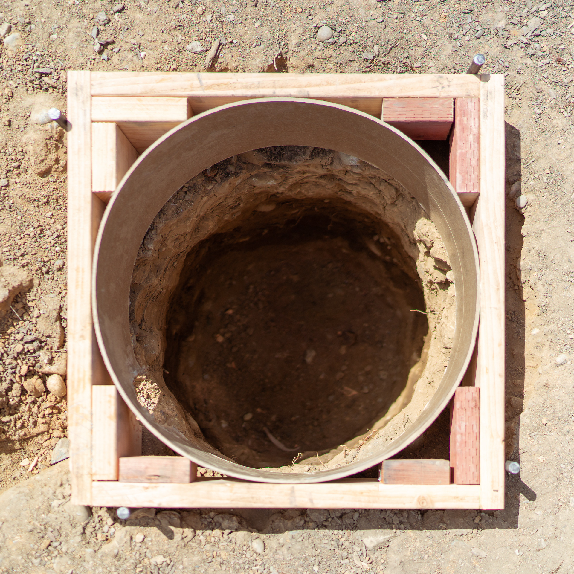
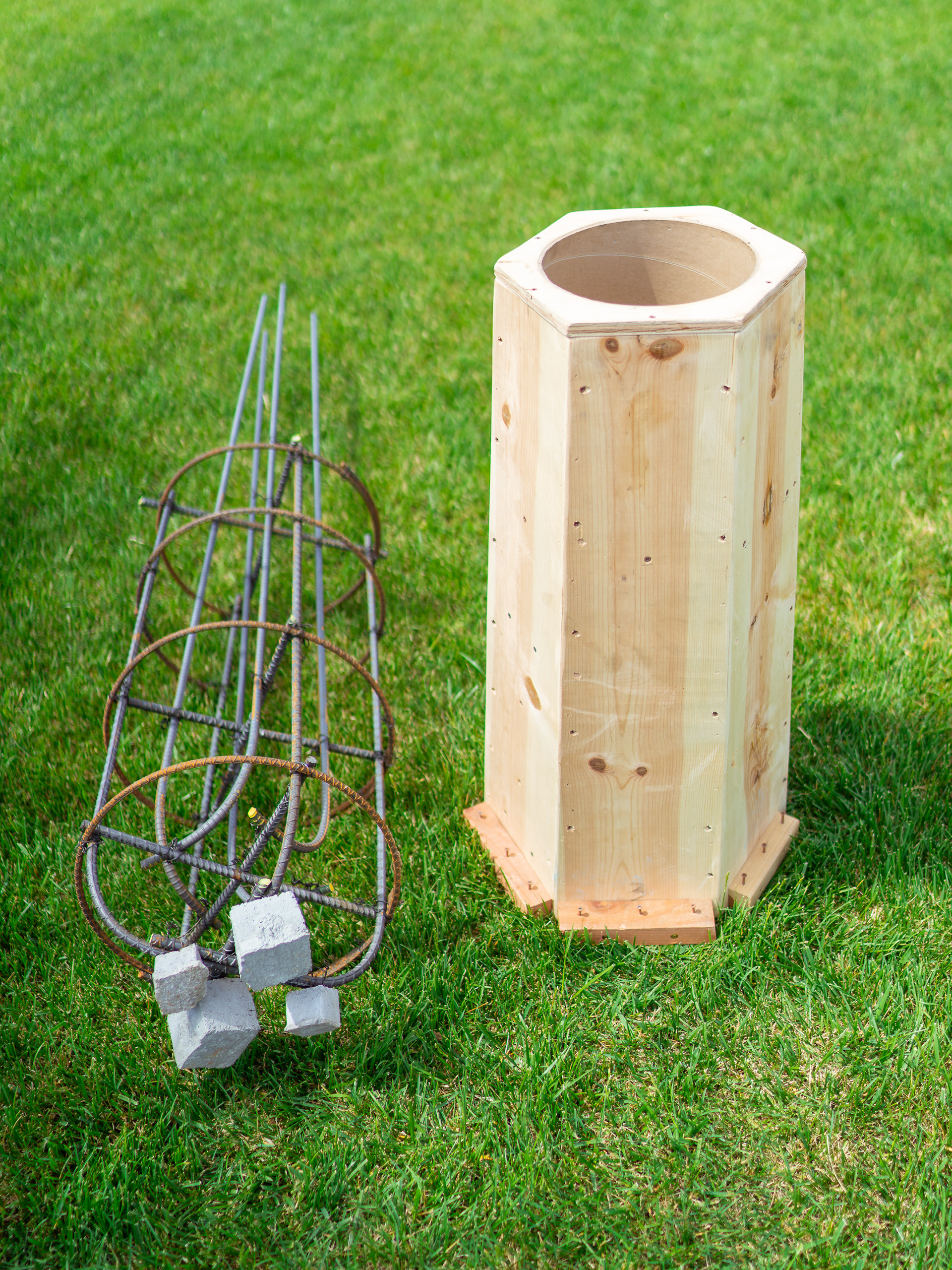
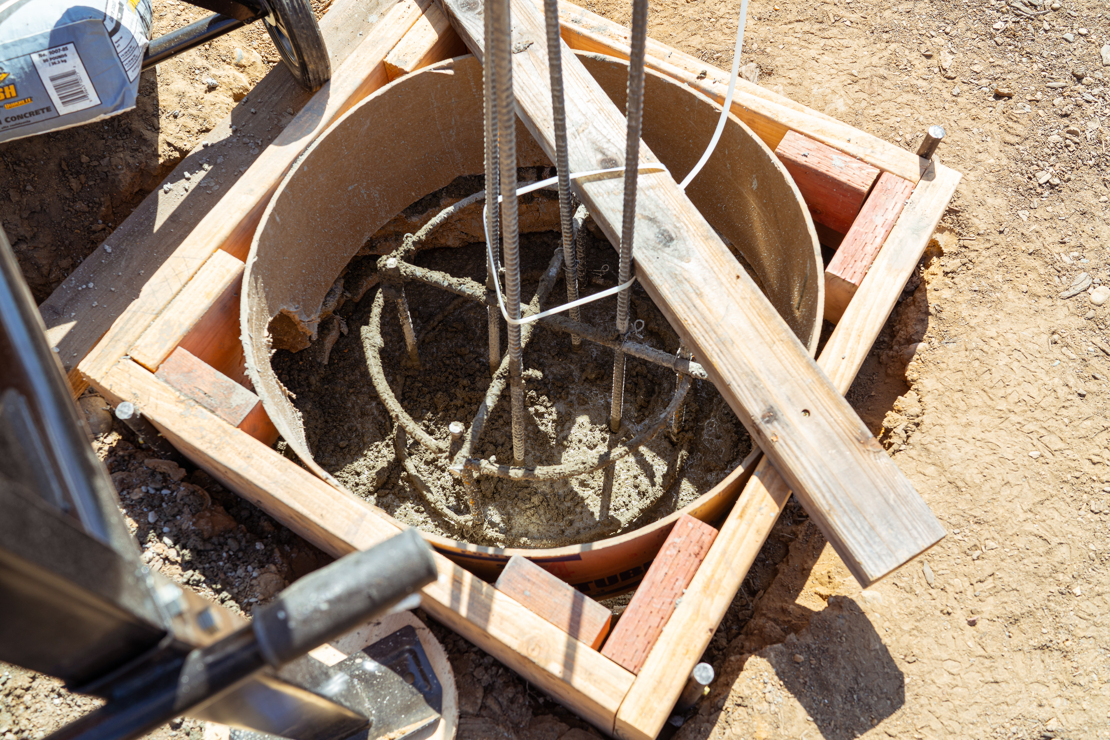
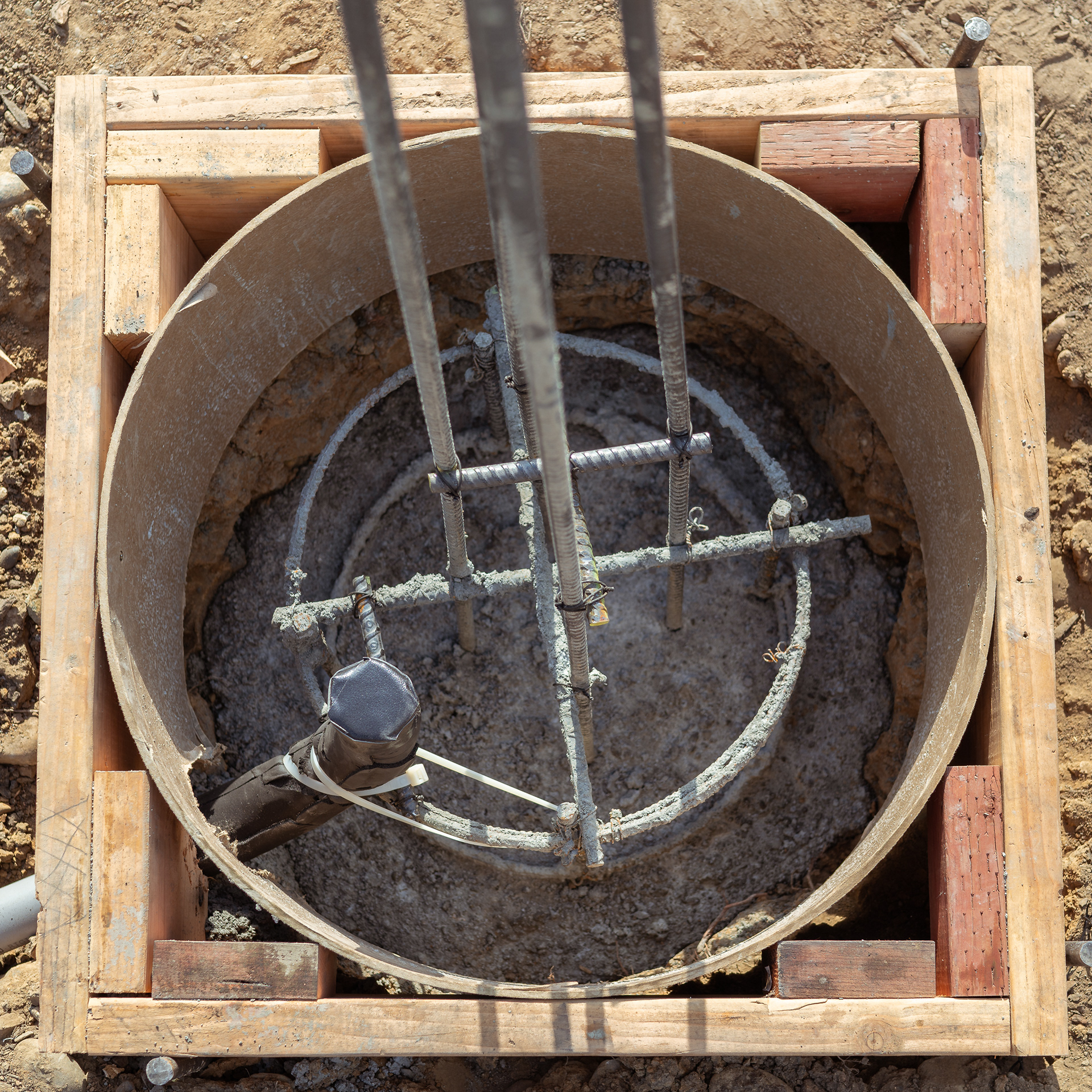
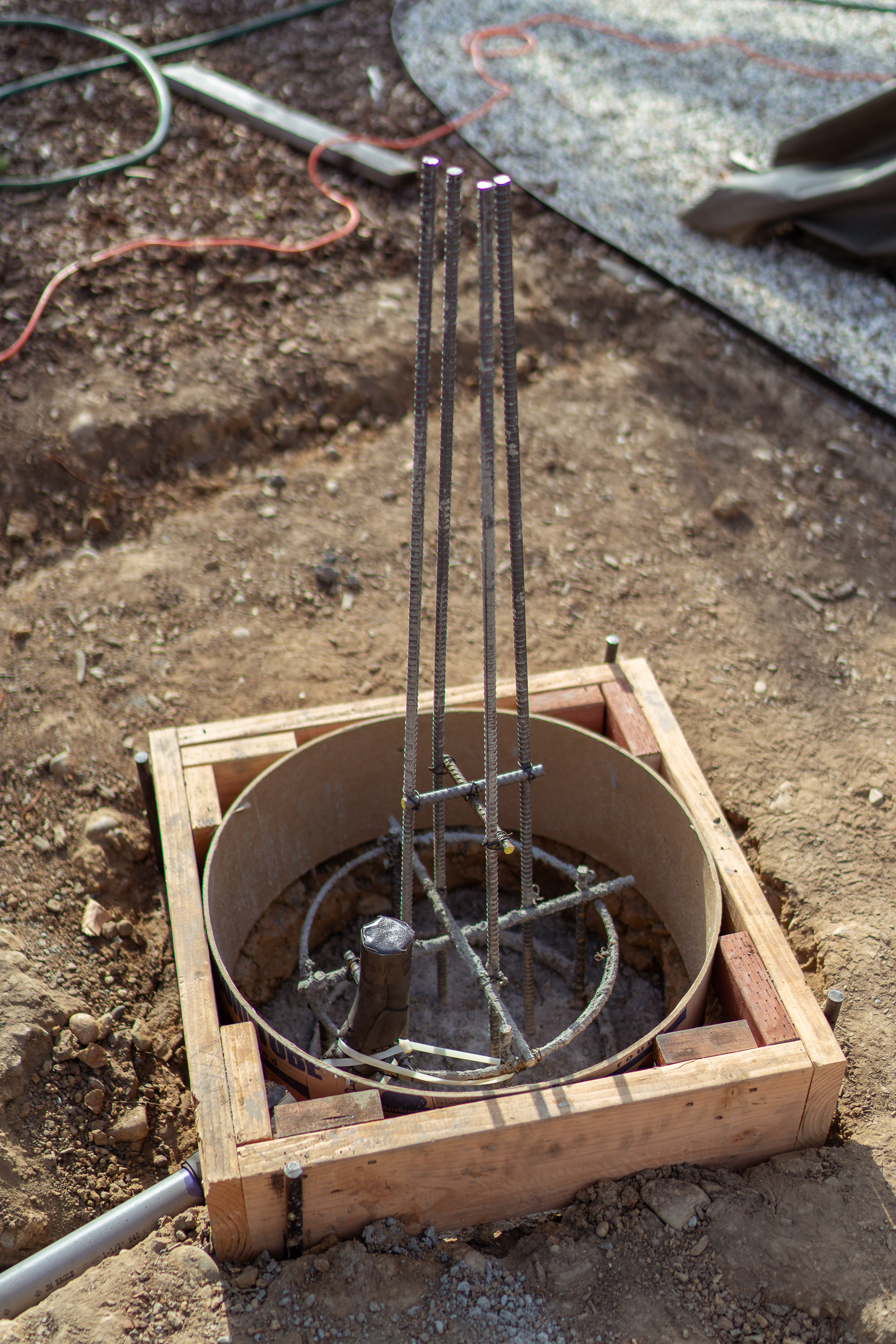
Next it was time to build a cage out of #3 and #4 rebar to reinforce the pier base and the pier itself. The perfectly round rebar rings were available from a local hardware shop and were the correct diameter to fit into 24" round base hole I've dug up. Since I was expecting to have some of the base stick out above grade, I've cut up a 24" SonoTube and used it to frame the top section of the pier base and secure it in place with a square box made of 2"x6"s. This was done for a nicer aesthetic finish and to contain the foundation diameter to 24" without spilling over. This square box form also provided solid foundation on which to secure the pier form above and help with leveling the pier column perfectly upright along with proper North alignment later.
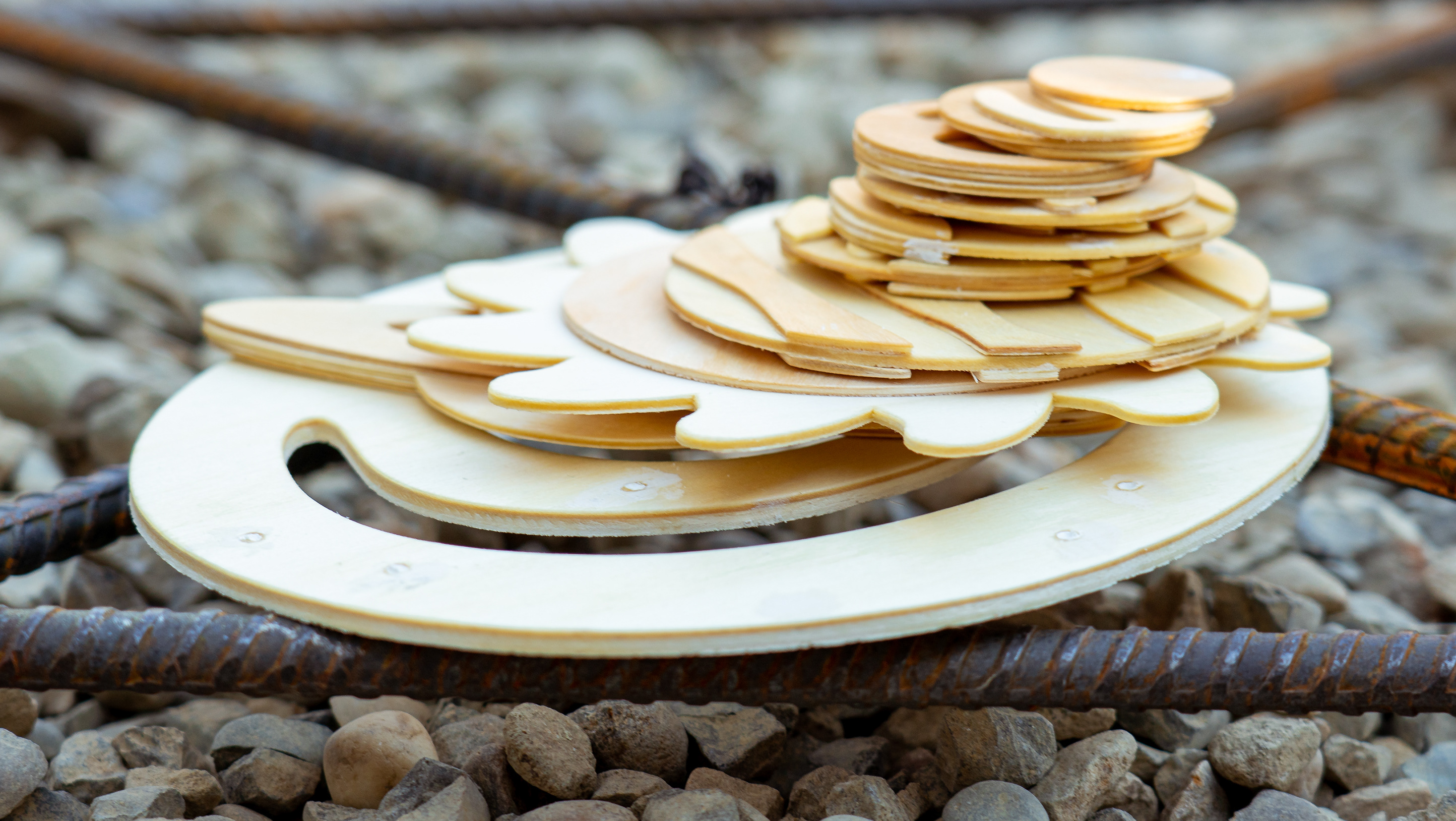
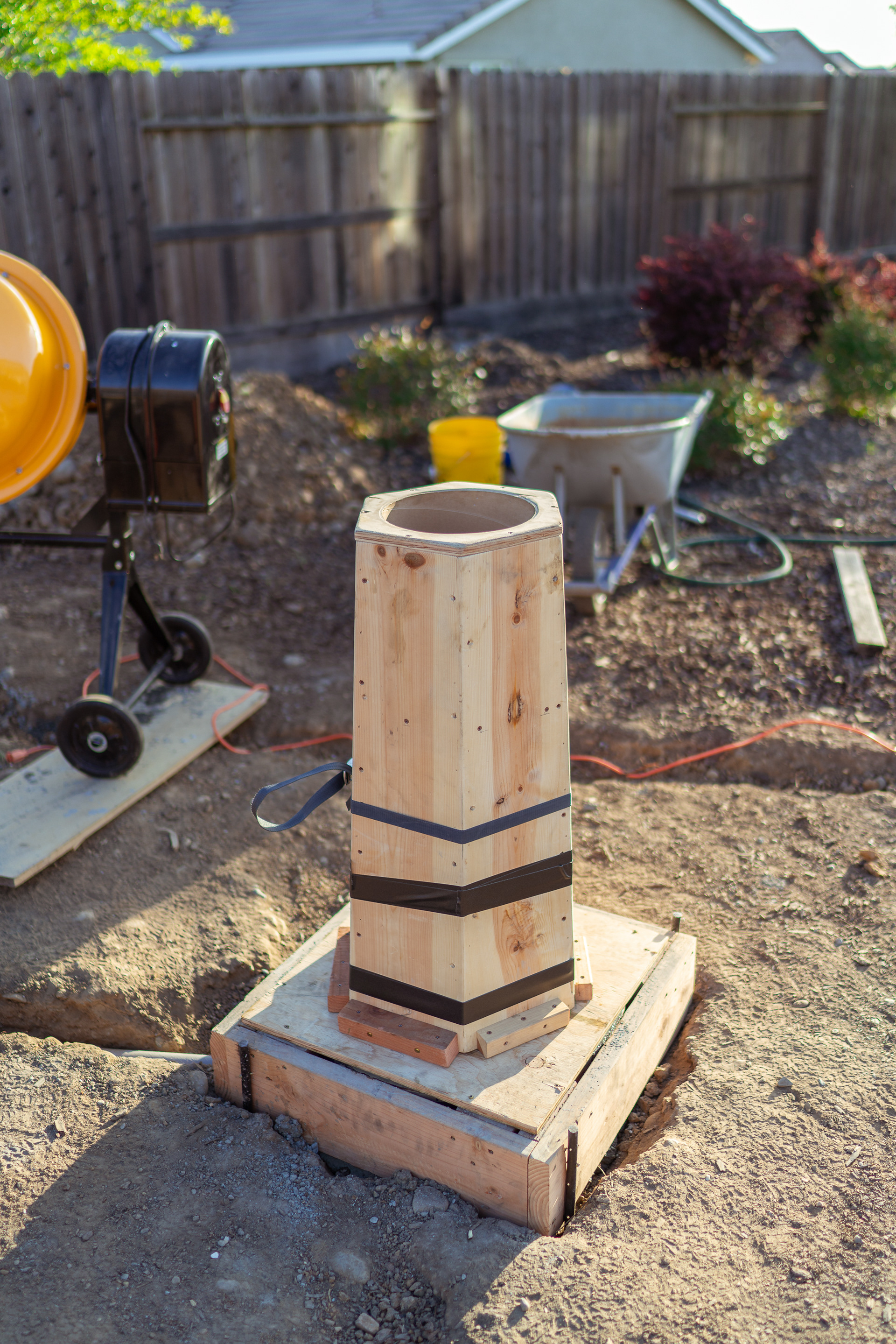
I then decided to make the pier a bit more interesting than a typical round12" SonoTube column and formed a hexagonal shape which I've cut out of plywood, screwed and stapled together. The resulting pier pier structure as follows:
- 2' x 4' pier base below grade - reinforced by rebar cage section that is about 3.5'
- 3' hexagonal pier column above grade - reinforced by four #4 rebar section that is about 2.75'
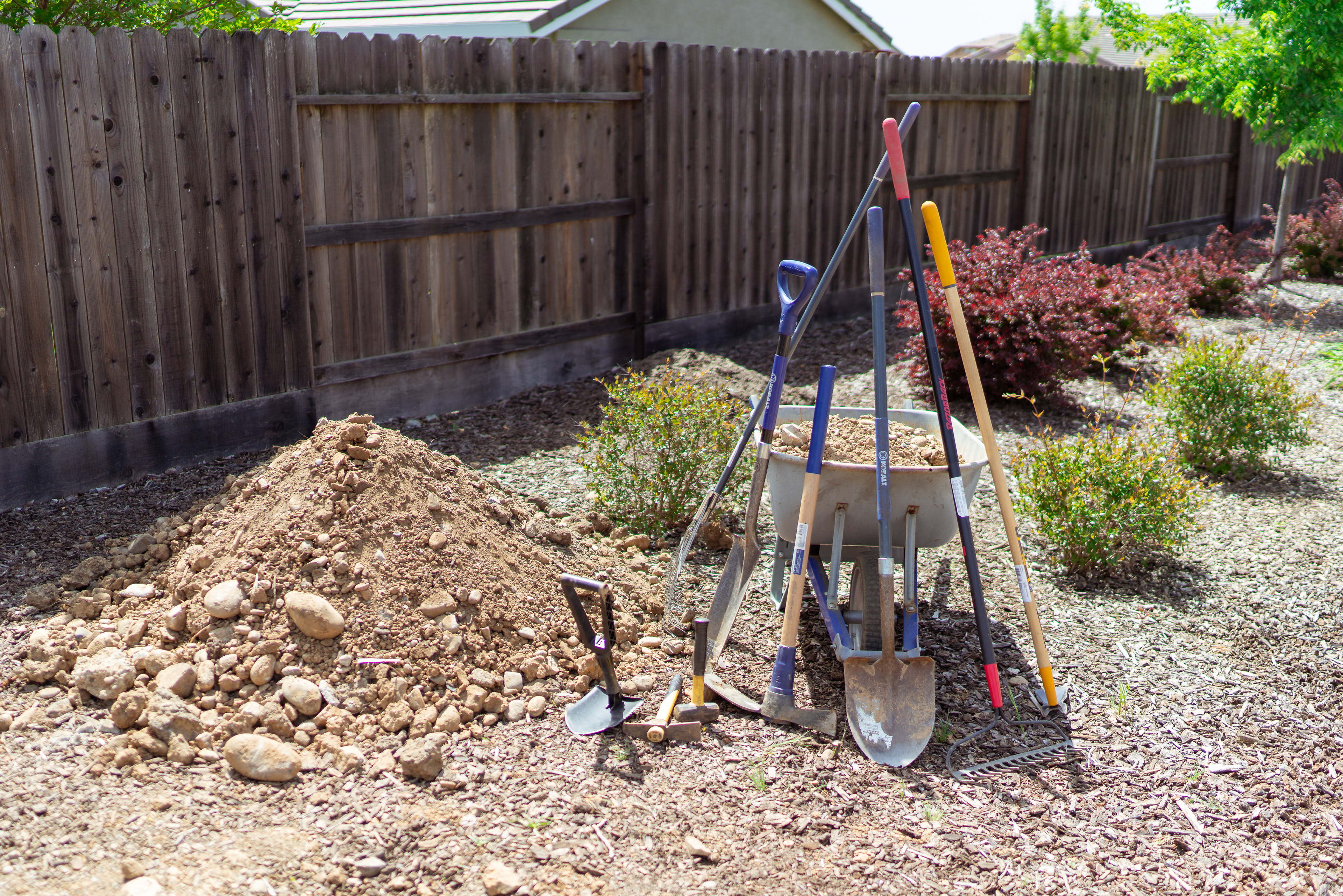
Aftermath... not pictured are the two heaping wheelbarrows of those big boulders that my neighbor hauled away to his rock garden already...
Pier base will be poured against native soil
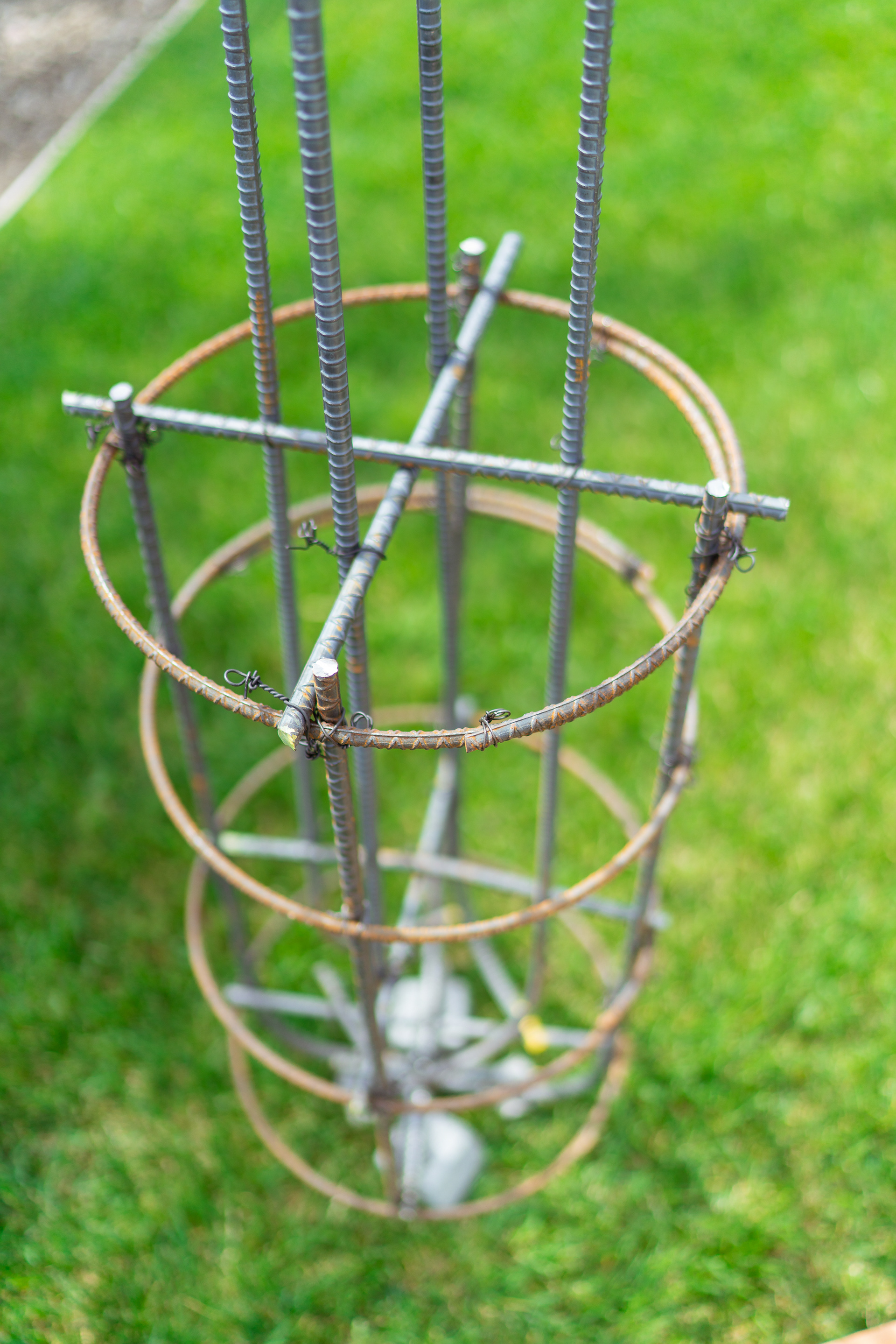
Base cage
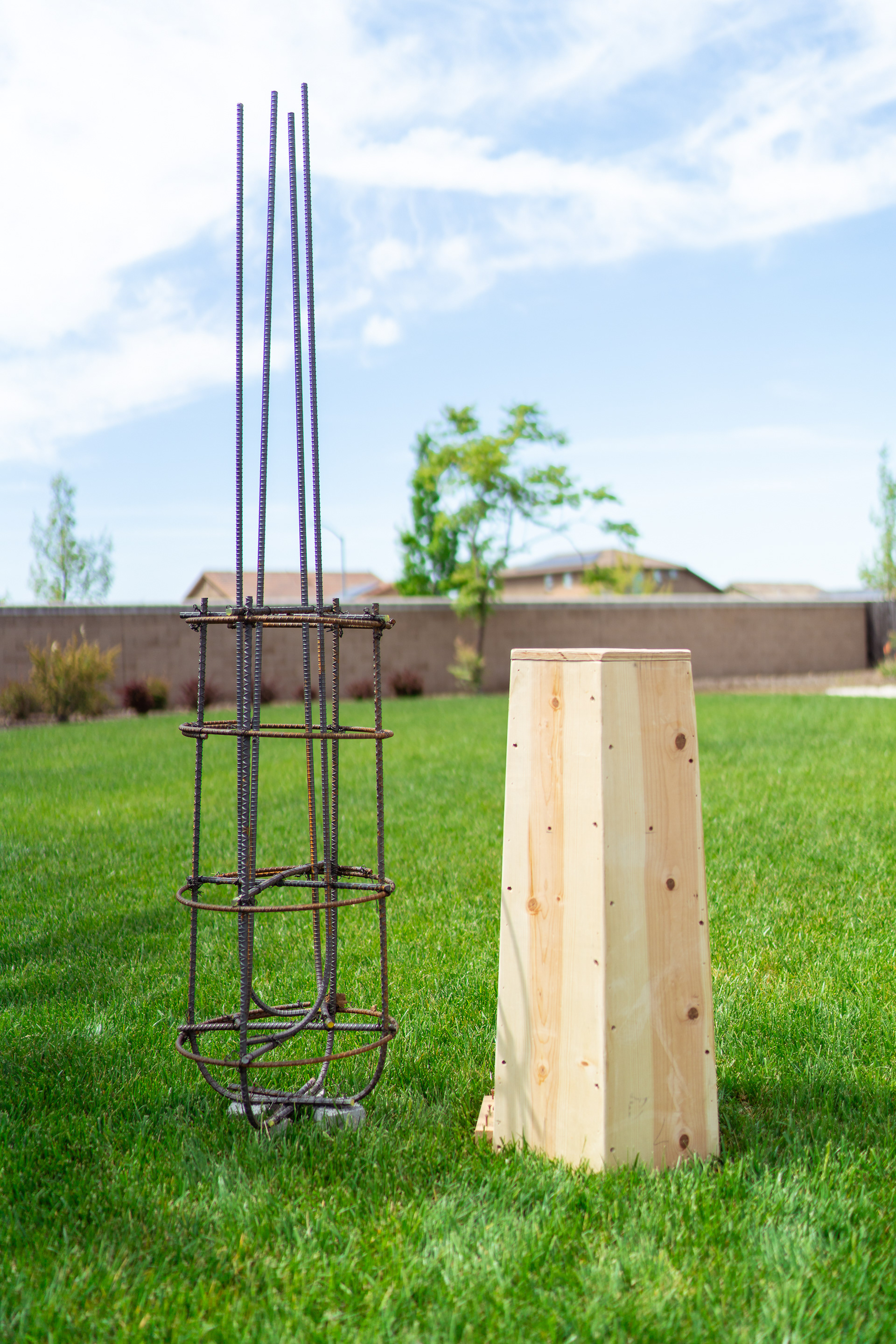
Cage next to pier form
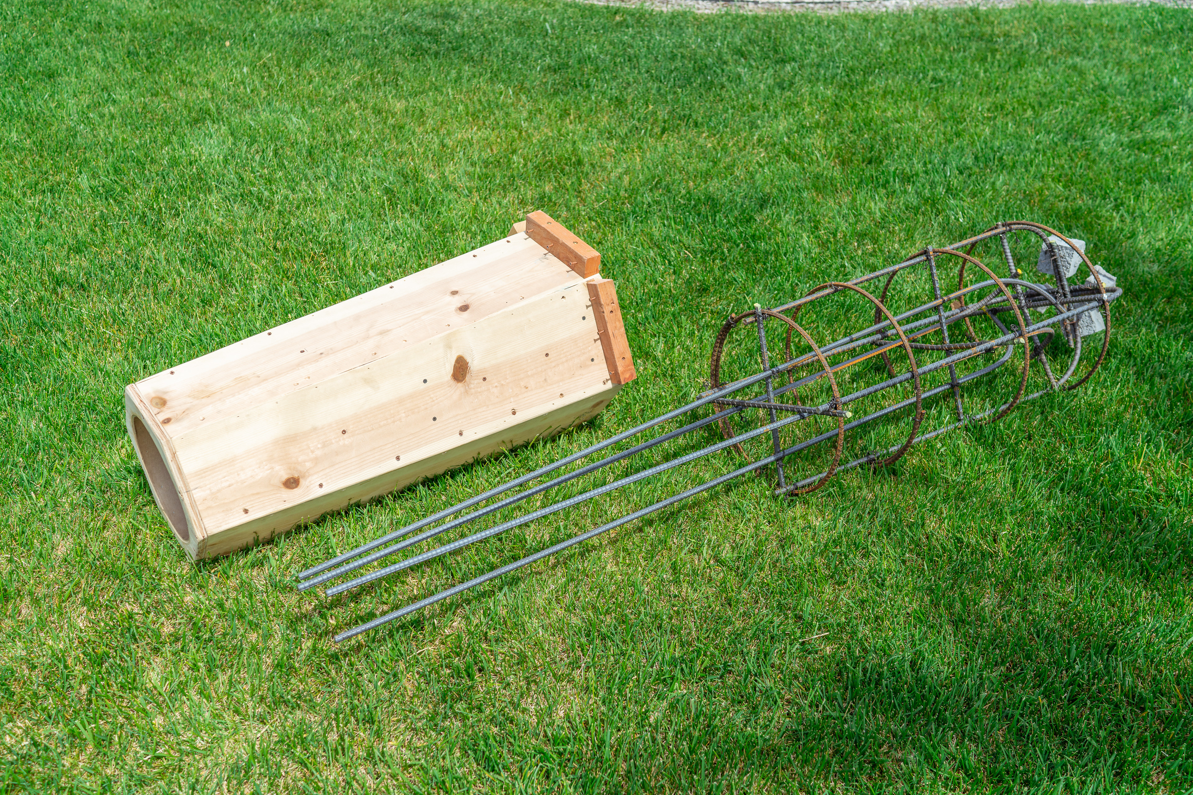
Alternative view
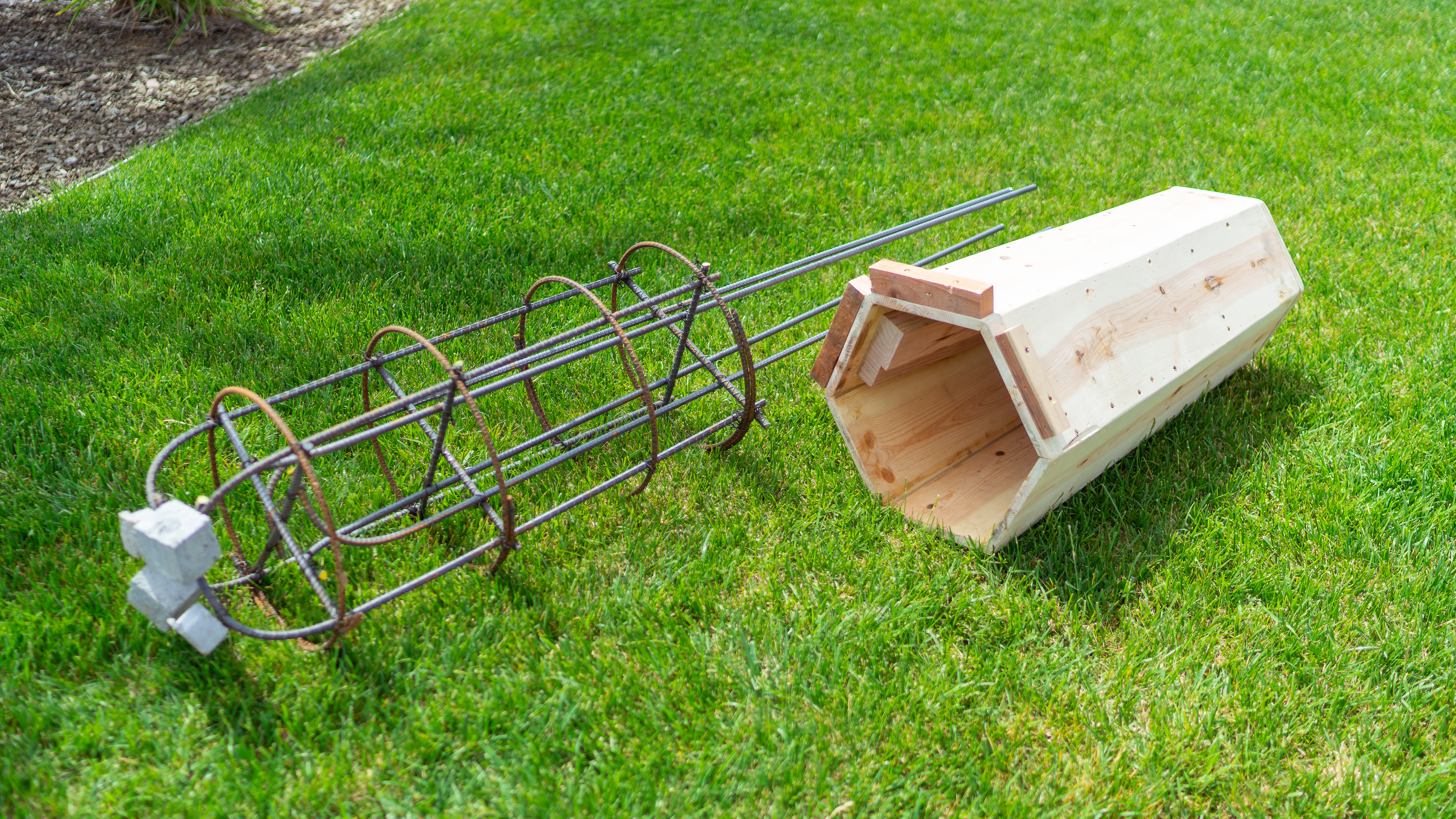
Alternative view
One more view...
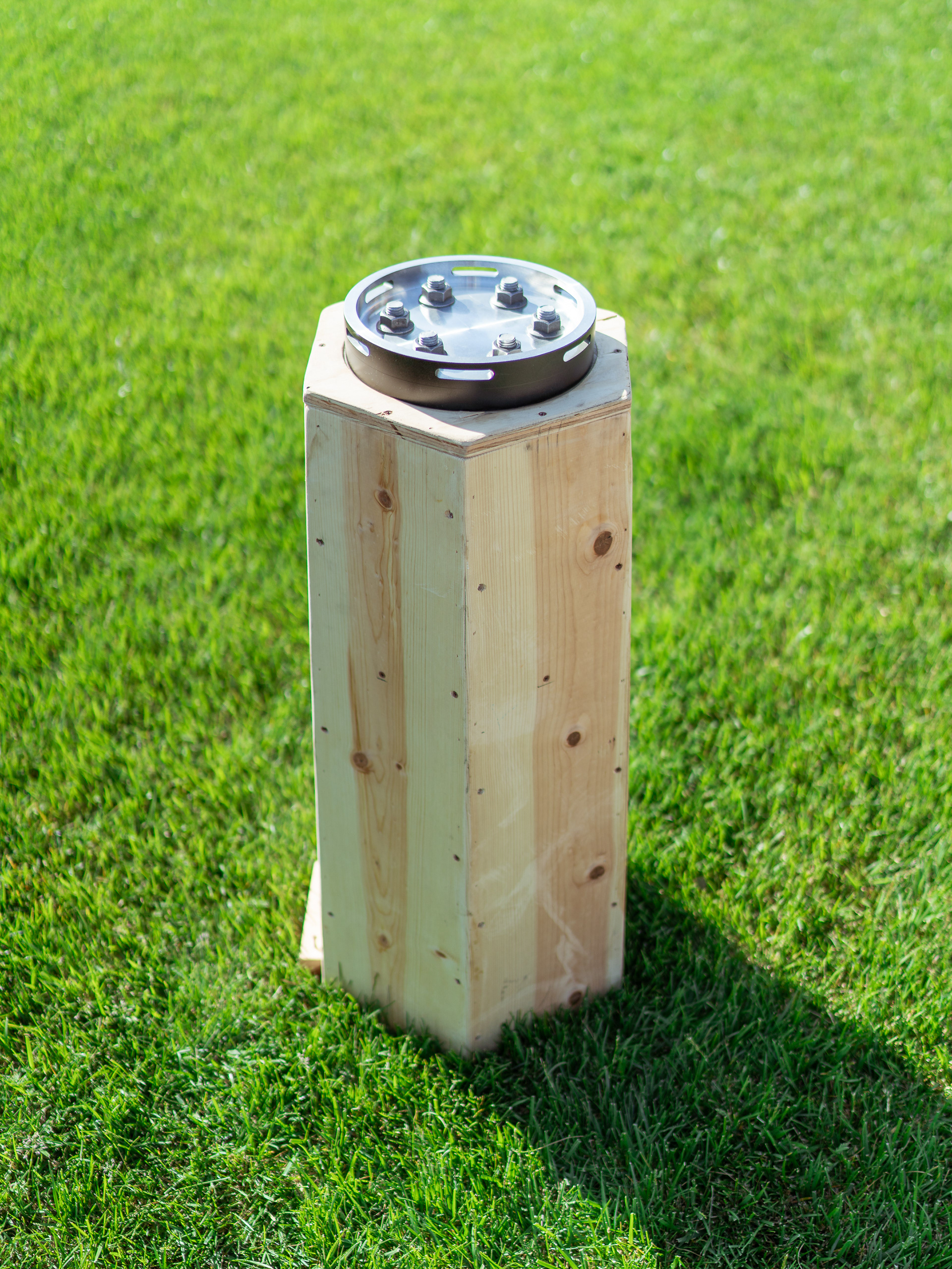
HEXAGONAL PIER...
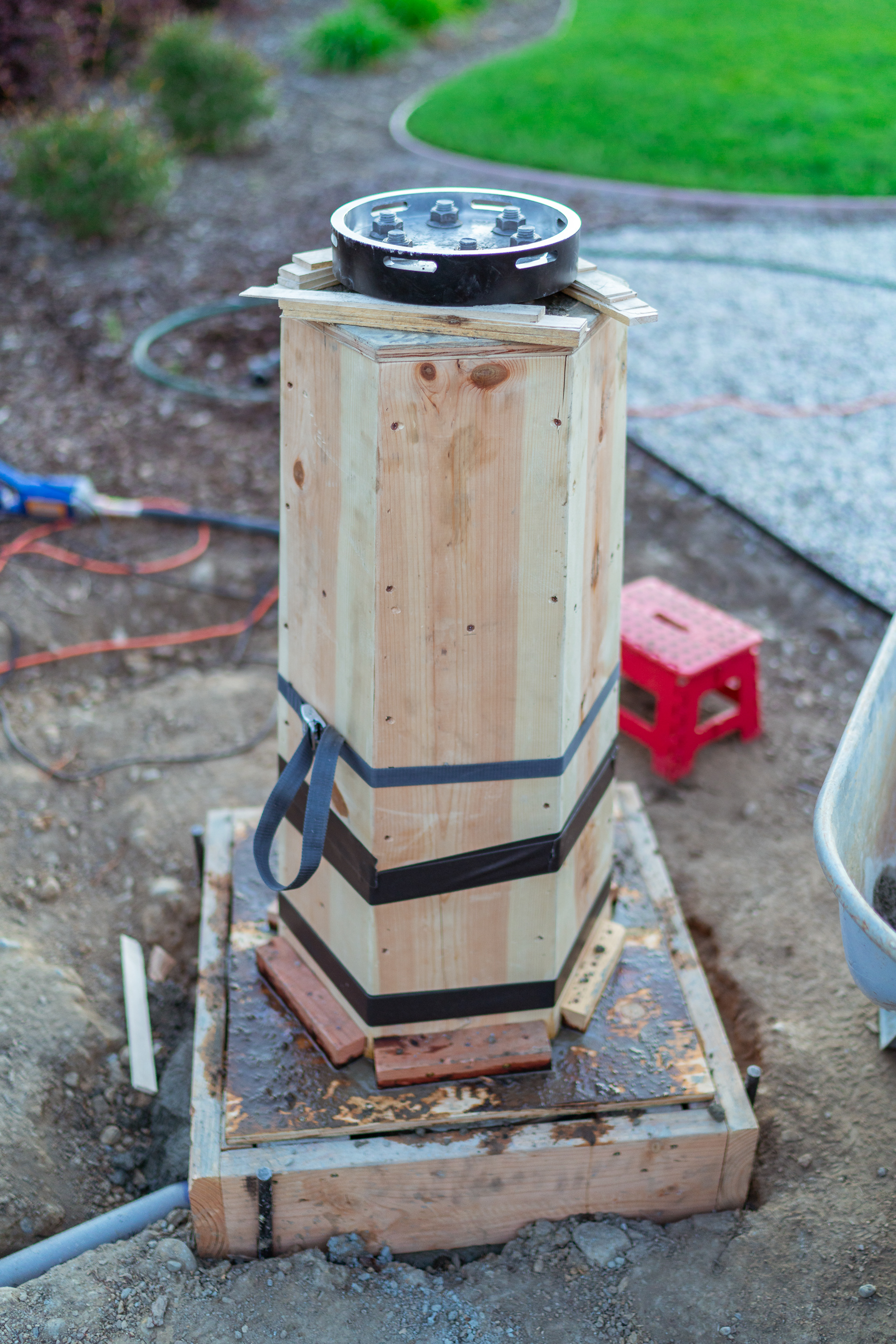
The resulting pier column ended up being a tapered design with about 16" diameter on the bottom and 12" at the top. After measuring things out, I decided that the 12" hexagonal shape might present some clearance issues with longer refractors so I've reduced the 12" hexagonal top down to a 10" round shape by fitting in a 10" SonoTube inside. I have sanded and sealed the interior of the pier and then installed some protruding planks to make a cavity for housing power adapters. The protrusions were measured against a planned 2" conduit pipe that would be imbedded in the pier and running under the floor slab.
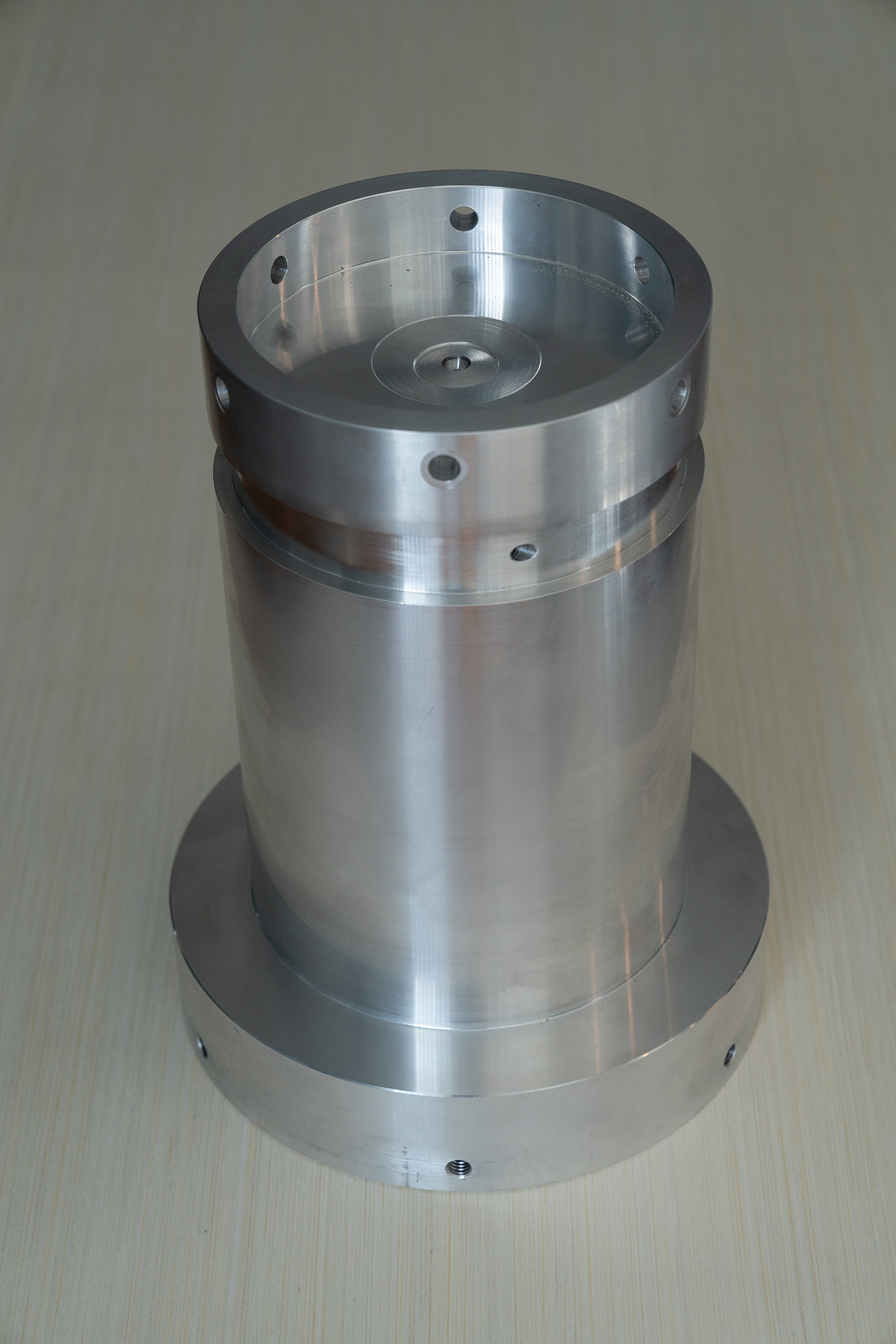
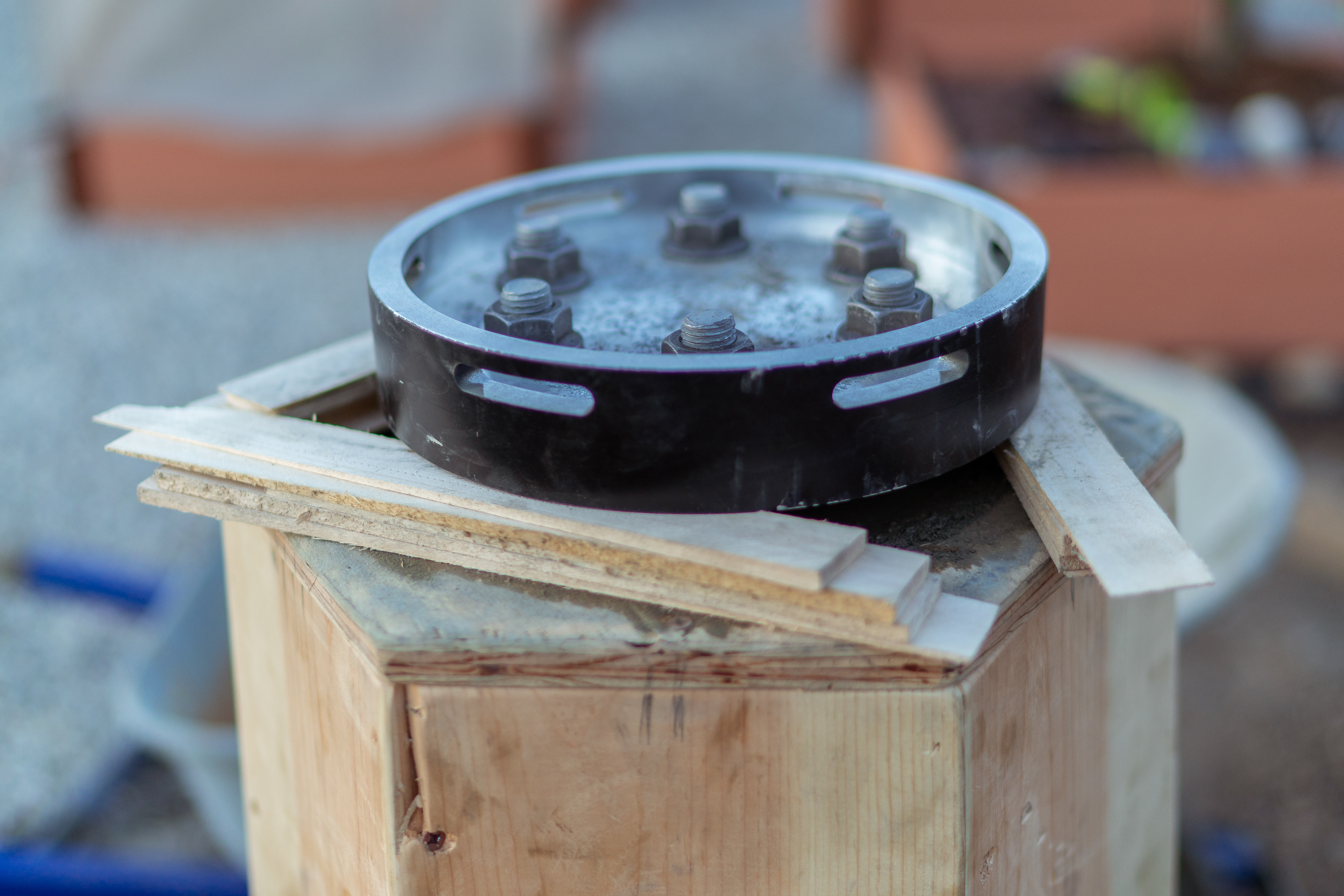
I've tested the alignment and fitment of the mount adapter plate (my own custom design) next.
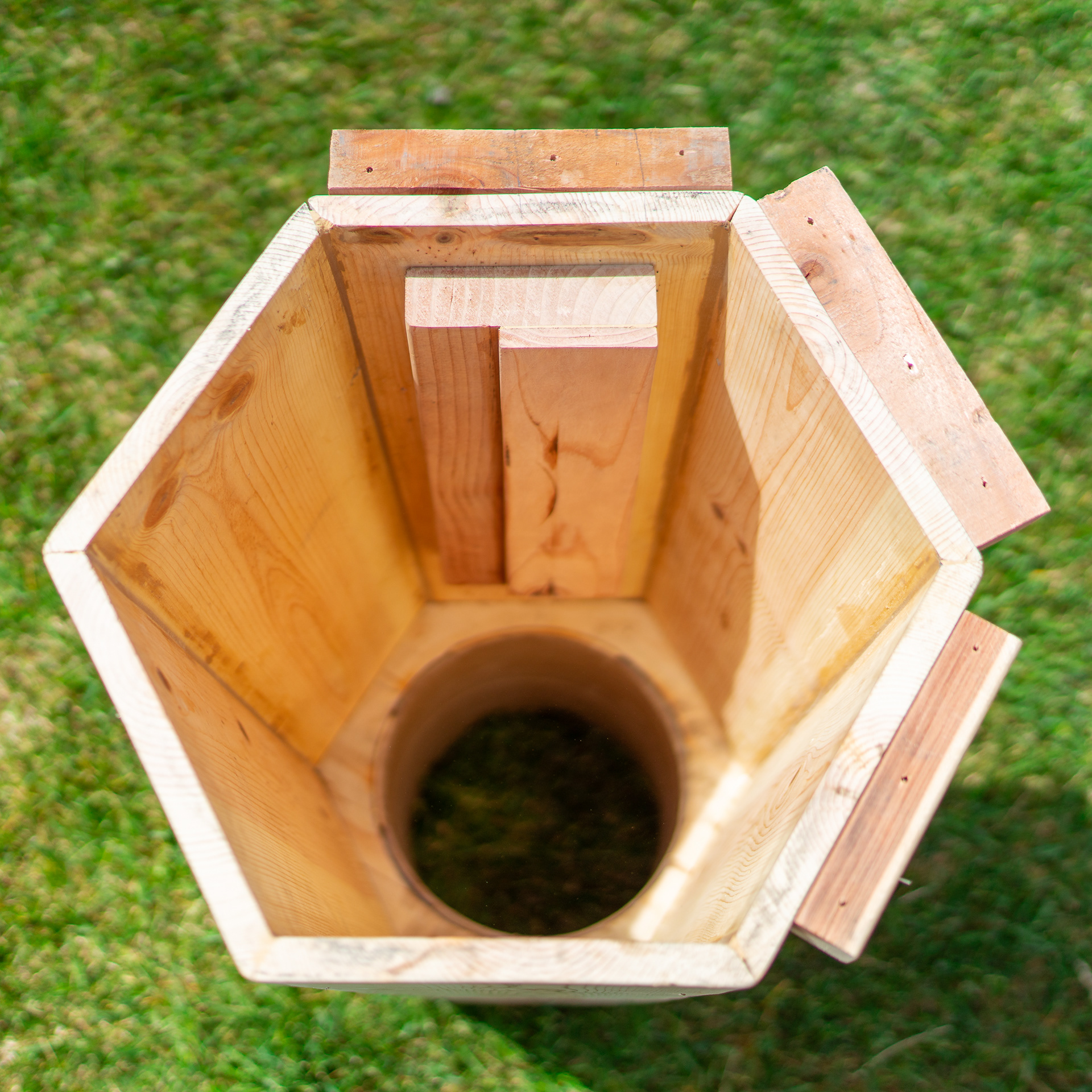
Pier form from below
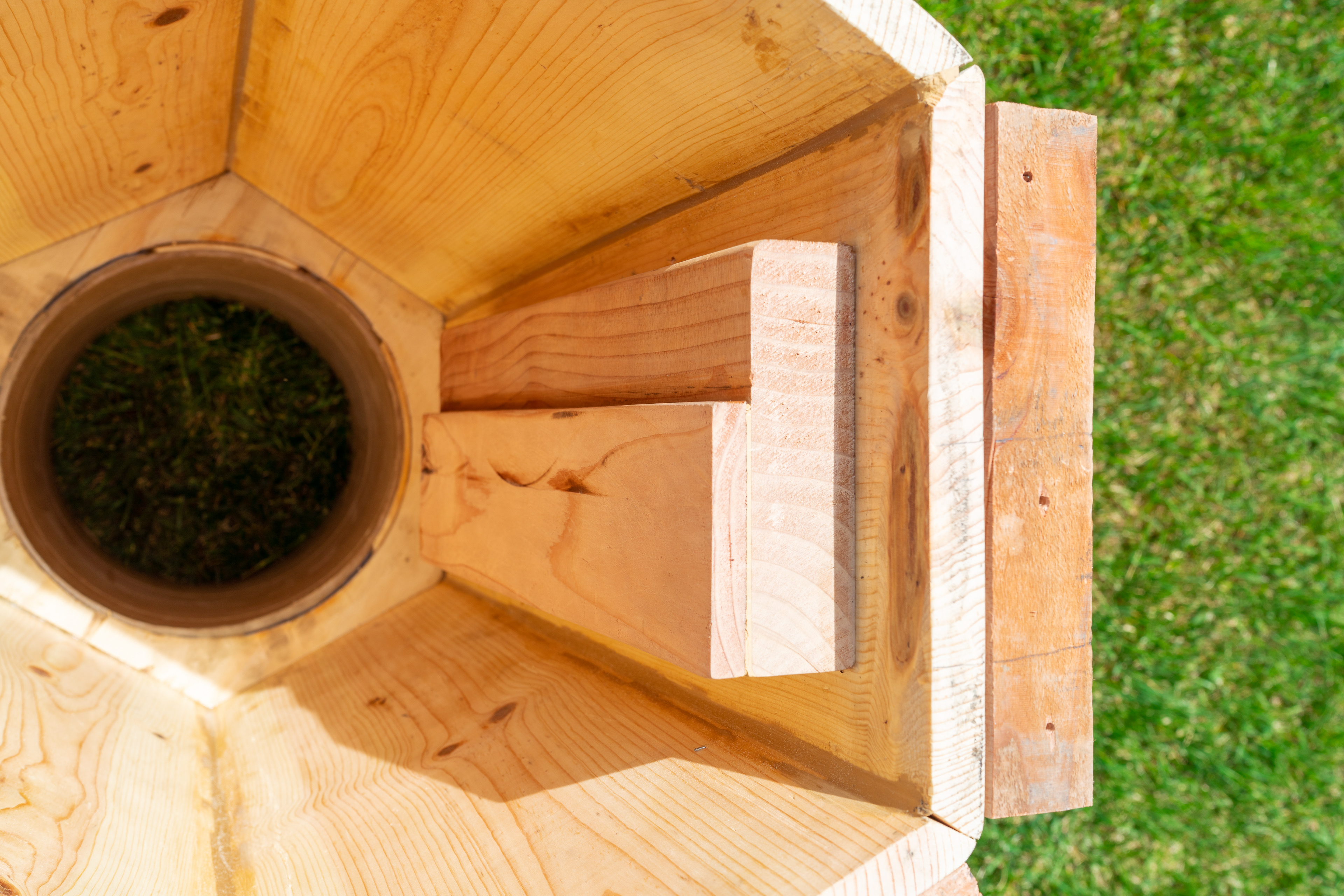
Protrusions to make room for power adapters

10" SonoTube to reduce diameter at the top
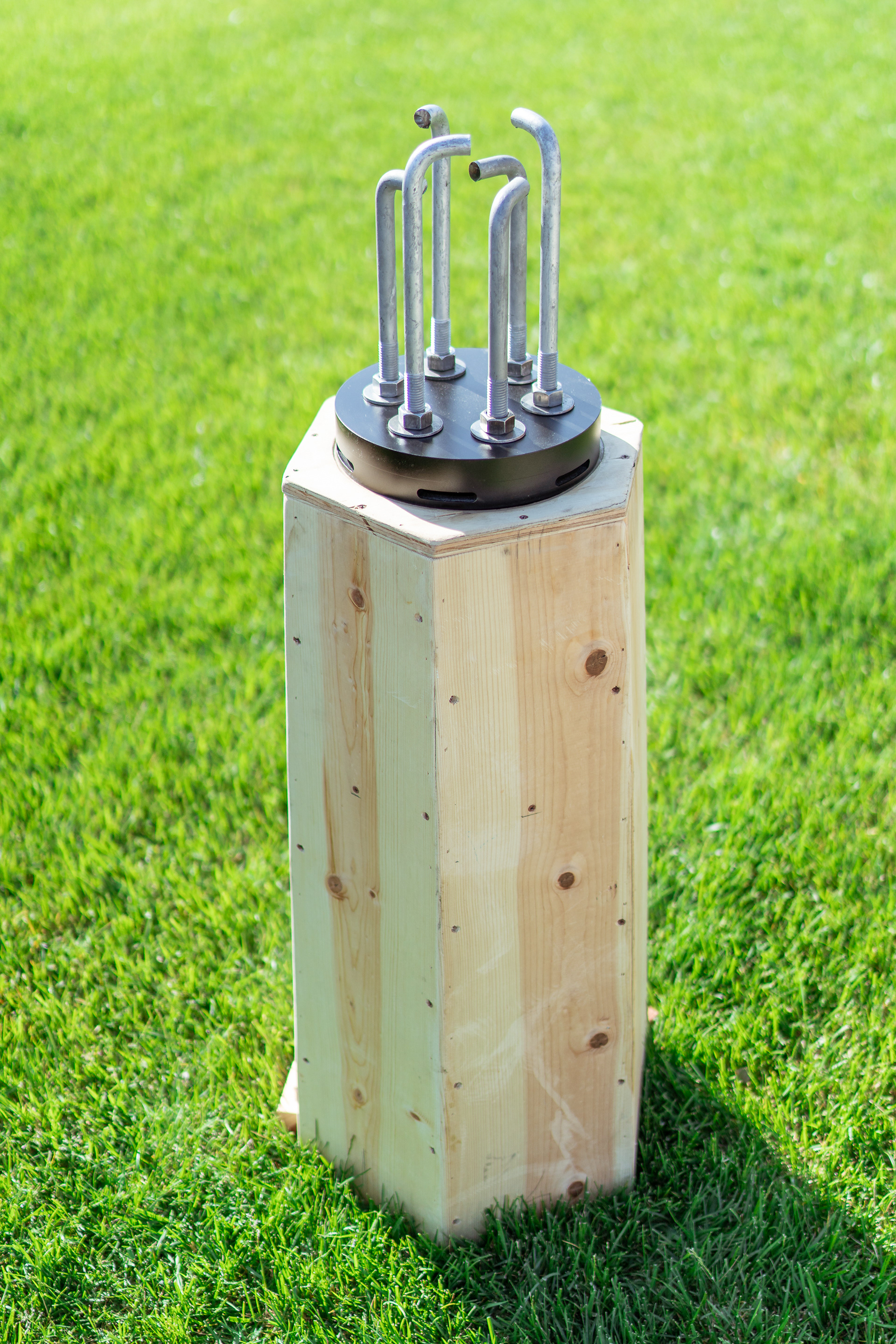
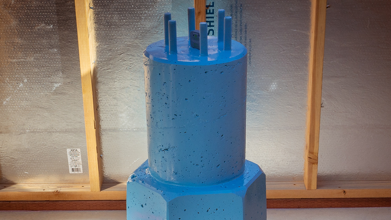
This is what will be imbedded into the pier
...with J-bolts down
10" mount adapter plate
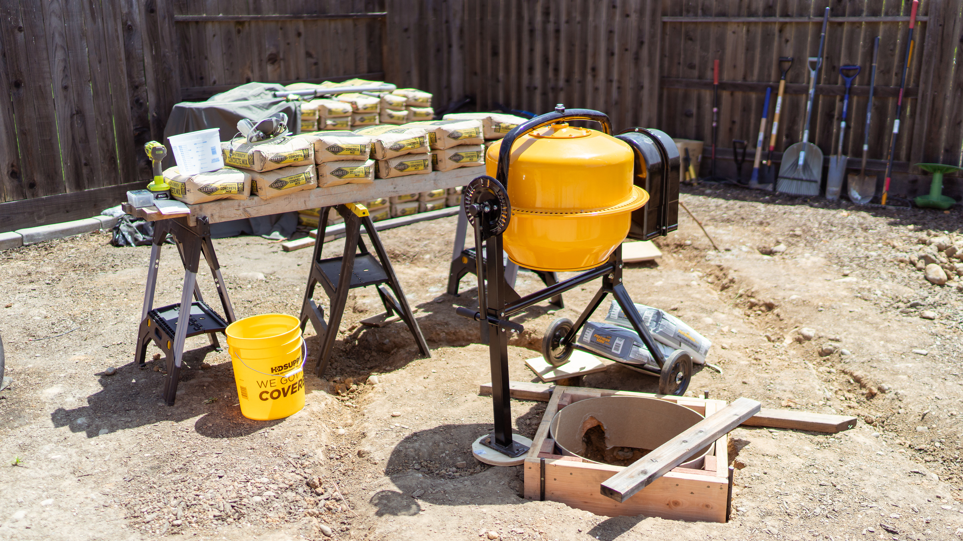
TIME TO POUR...
I have never worked with concrete before. Few YouTube videos later I felt like I can tackle this basic pour, as it's really just a mix and pour job. Since I was planning on pouring the concrete slab foundation myself, I figured it would be worth my while to purchase a simple mixer and I ended up with a HomeDepot special that can easily mix 3-4 bags at a time. In addition I invested in an electric concrete vibrator which quite literally made all the difference when it came to making sure the pour was nicely compacted without any excessive air bubbles... $56 well spent.
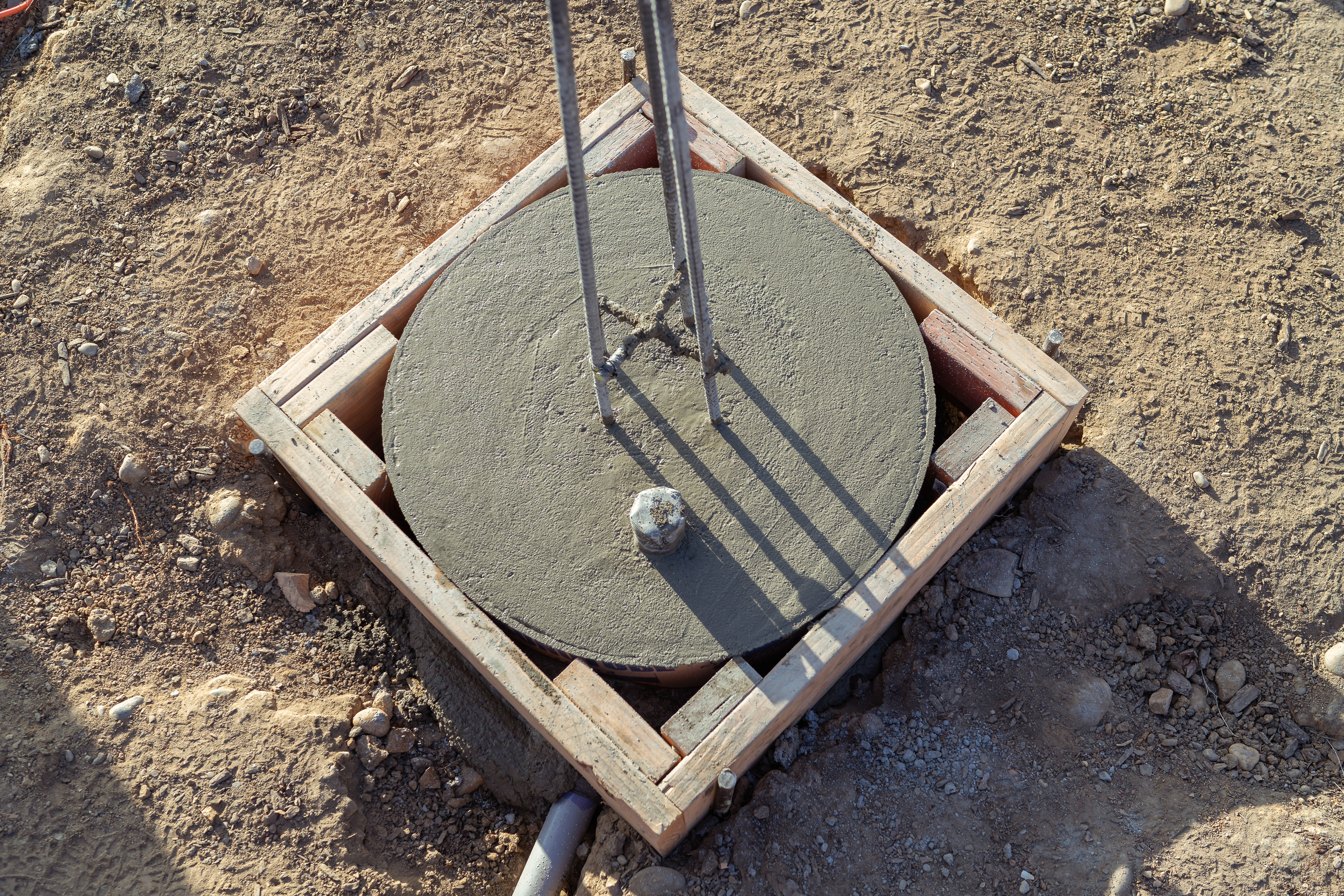
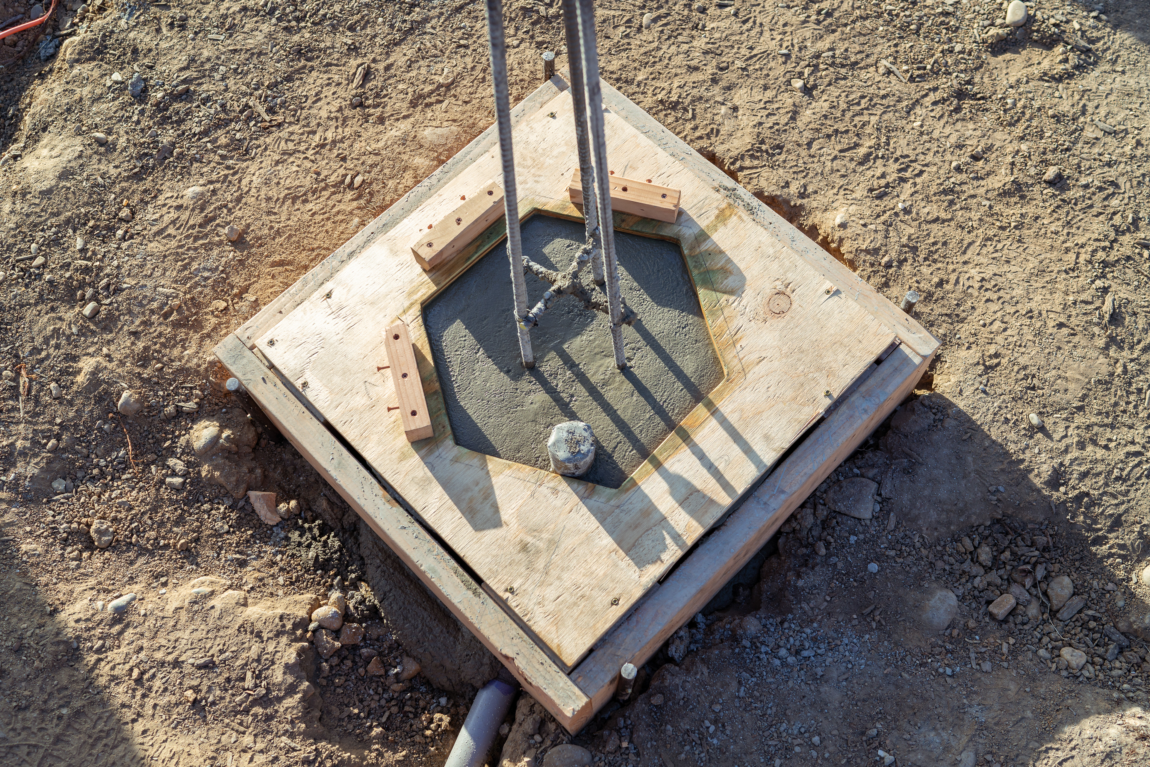
I decided to break the pour into two parts... first part was to pour 4/5th of the base and secure/center the cage. The next day I finished second part and poured rest of the 1/5th of the base, then secured and leveled pier form base, column form and poured the rest. I did use a whole bottle of cement glue to help with bonding between the two pours. Standard 4,000 psi Sacrete mix from HomeDepot in 60lbs bags for the 1st pour (18bags) was used, and 5,000 psi High-Strength mix in 80lbs bags for the 2nd half of the base and the entire column (6.5 bags). If I did my bag counts right, I believe the entire pier came up to at least 1,600lbs.
Hardest part, which put me in near-panic for about 20 minutes, was at the very end when I had to insert the mount adapter plate with anchoring bolts: the concrete slurry was very hard after I compacted it with the vibrator and that made it nearly impossible to maneuver the bolts in. I ended up using the vibrator to "hammer/vibrate" it in the fresh concrete, which did the job.
I left the whole setup cure for a few days before taking the forms off.
All is ready for a quick and simple 1st half of the pour
1st half poured and rebar support cage centered
Conduit pipe centered
Ready for the 2nd half of the pour
Pier base is now poured and ready for the rest of the column
Pier form platform is mounted and leveled
Pier form secured and ready for pour
Pier column poured
Mount adapter plate leveled using simple shimmies
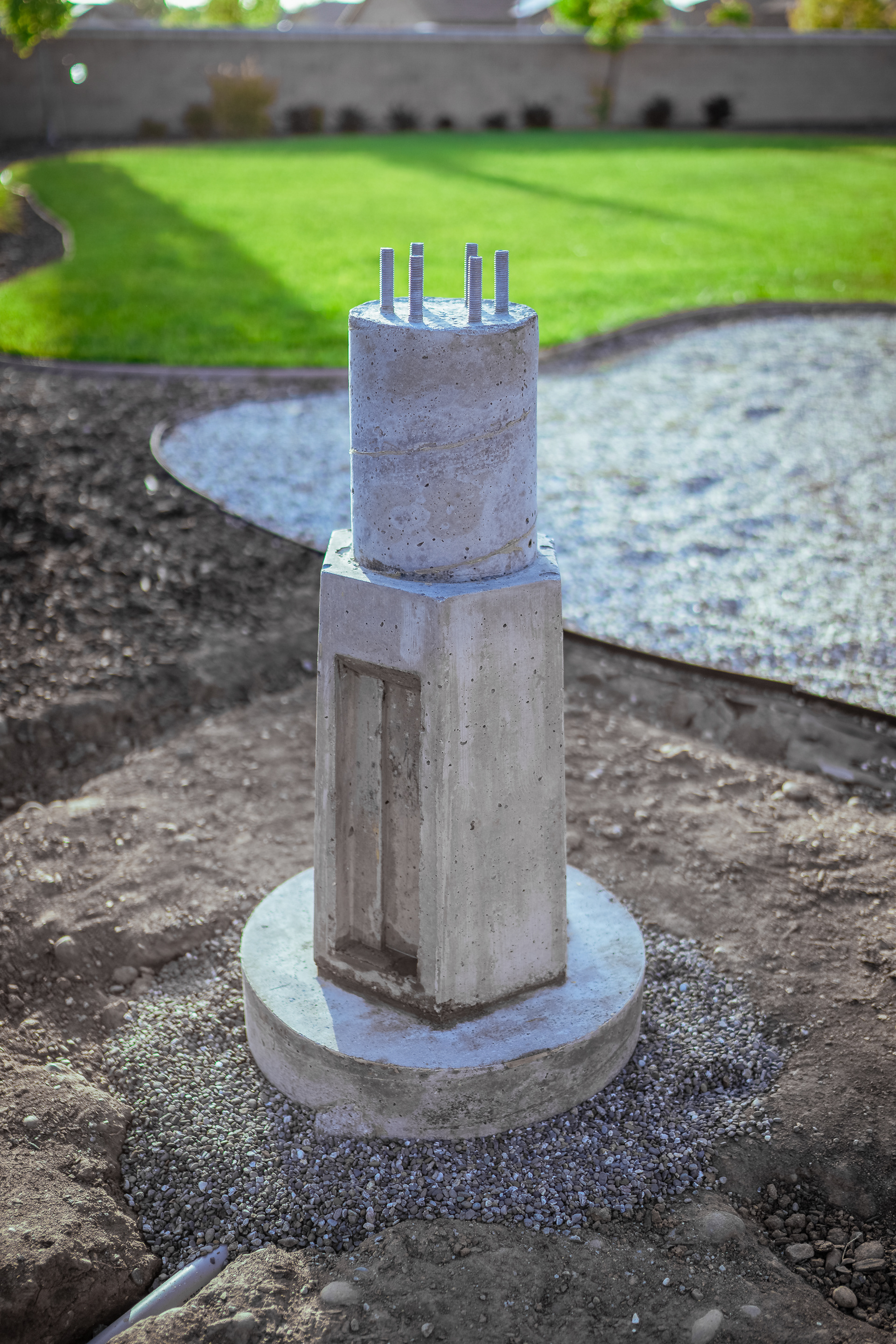
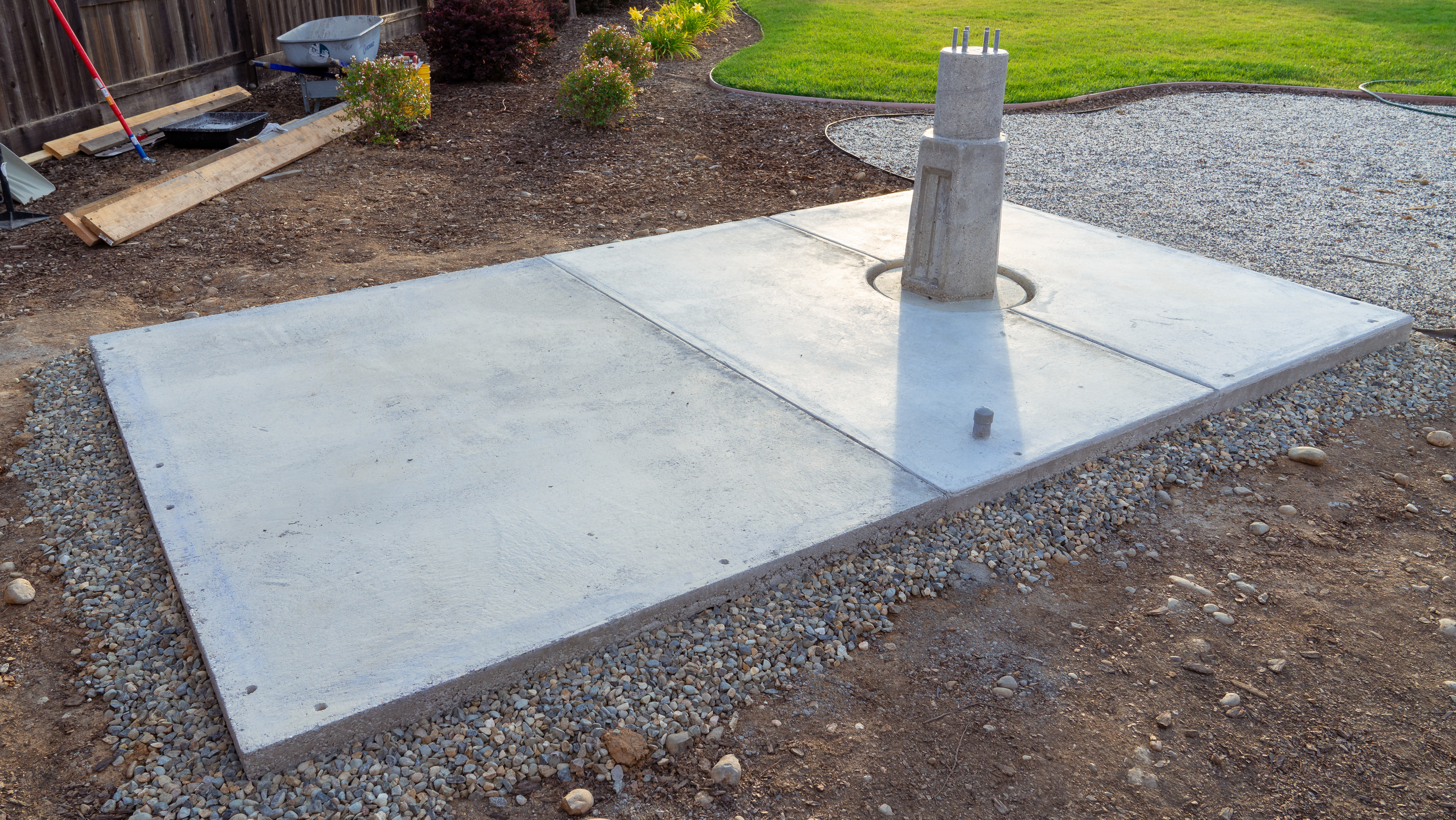
Done and done...
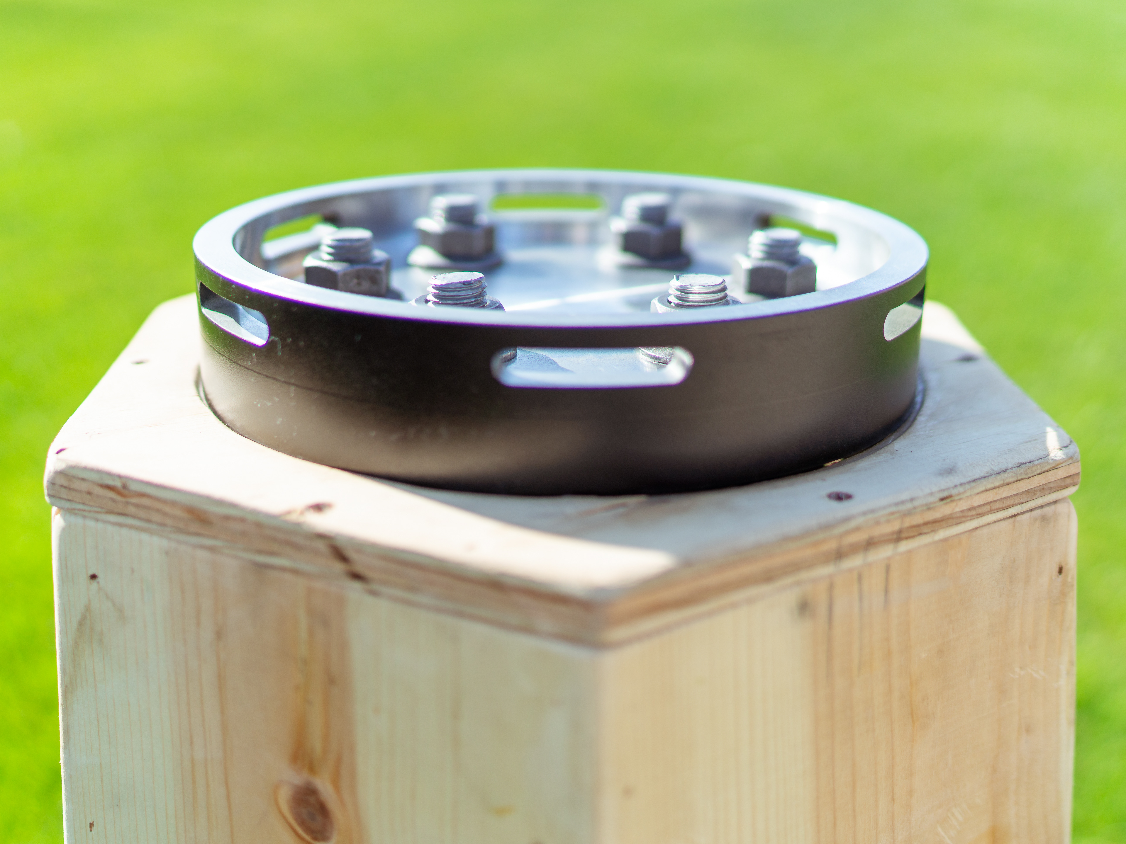
ABOUT THAT MOUNT ADAPTER PLATE...
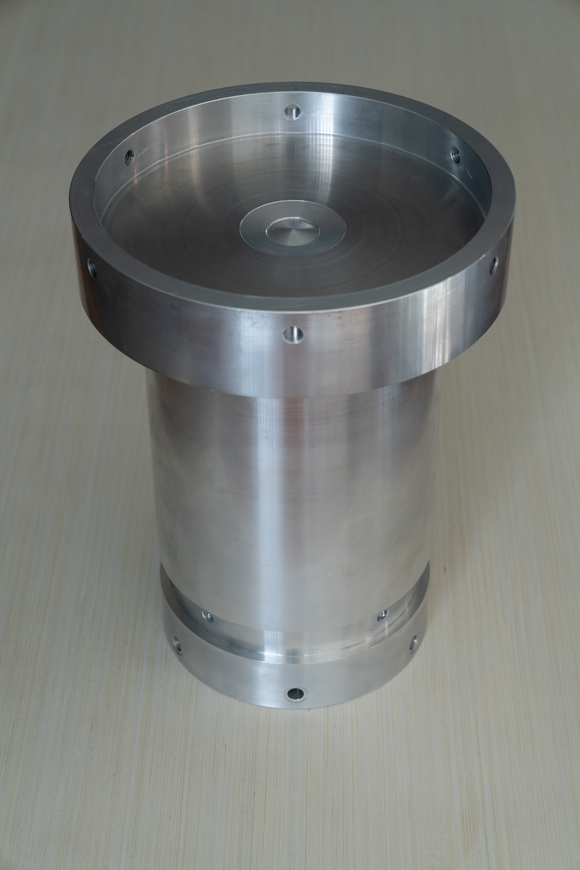
When I started researching how to build a pier I found that most designs called for what's known as a "rat cage"... a design that incorporates mount adapter plate sitting on (usually) 3 tall anchor bolts. The design is somewhat controversial as the bolts on which the entire mount/scope setup sit above can potentially deflect, laterally, and/or be prone to magnifying some vibrations. To mitigate any potential issues common to the "mount-on-stilts" contraptions, I designed a plate that would sit directly on the pier, and instead of having the mount bolt from the bottom, it would bolt from sides, as you see in the pictures. This would completely eliminate the "rat cage" and give me a much more solid foundation. While I was at it, I decided to design a 12" riser on which I would then directly mount a Losmandy G11 mount. Reason for the riser is simple: if I ever decide to upgrade to a larger and likely taller mount in the future, I would have some room to work with and not be up against any heigh restrictions with a permanent building + dome.
I sketched my designs in AutoCAD I had a local machine shop mill out a plate and a mount adapter/riser out of solid aluminum. In retrospect, the riser was a total overkill and an unnecessary expense that I could have probably avoided by pouring a taller pier column and designing the mount plate to accommodate the mount directly. Lesson learned...
Also, in the end, I did not bolt the plate down flat to the pier - instead it's sitting about 3/4" above the pier top. This was a forced decision as I've struggled with pushing the plate/anchor bolts during the pour and frankly this ended up being a blessing in disguise - having the plate slightly elevated allows for proper leveling. Since I've used six 3/4" anchor bolts, there's virtually no chance of any meaningful deflection and/or vibrations - the entire structure a total overkill as is.
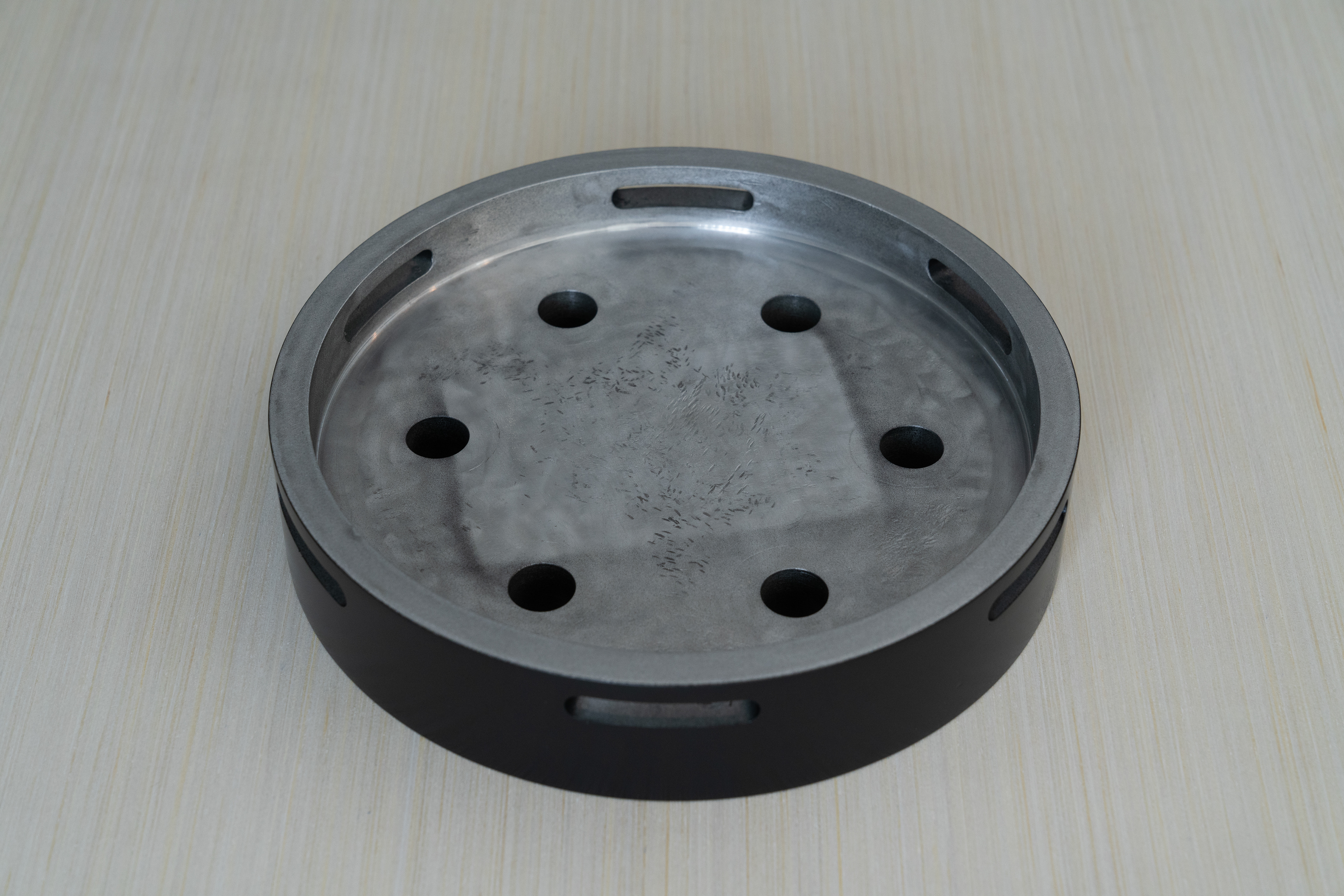
9" inner diameter
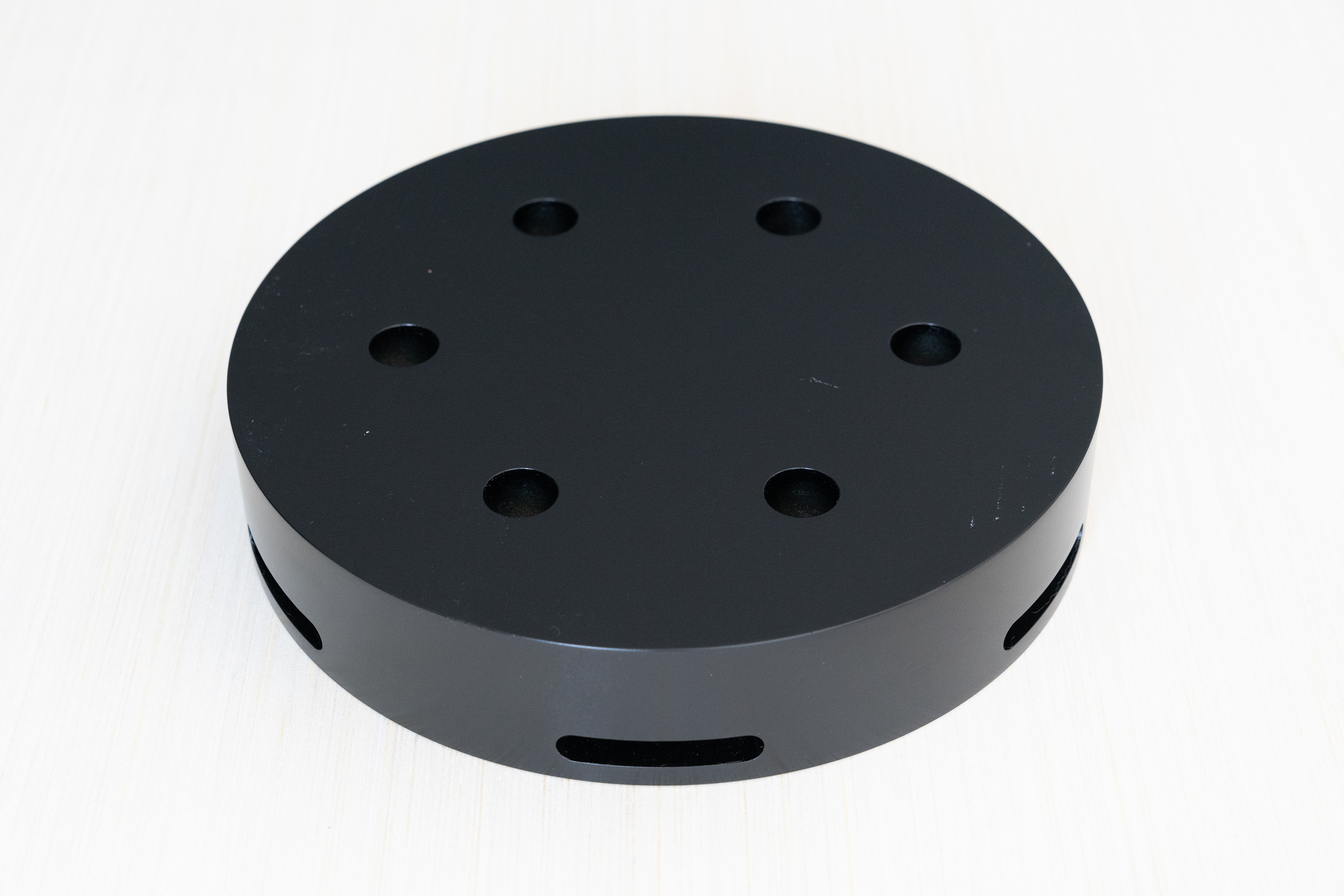
10" outer diameter
Bottom view